• The incoming protective earth conductor
should be connected directly to the back-
plate, and green-yellow conductors should
be taken from individual studs on the Back
Plate to the enclosure as required to bond
each panel that does not get a guaranteed
safety bond through the cabinet structure.
• Remove any paint or other insulating film
from the enclosure and the Back Plate, and
from the Back Plate at the mounting points
for the FP Filter. Refer to the illustration
below.
• All metal-bodied components are to be bolt-
ed directly to the Back Plate, metal to
metal. Any safety or other earth conduc-
tors should be as short and as thick as possi-
ble, and should connect directly from their
component to a stud on the back plate close
by, with only a single earth connection per
stud as directed by EN 60204-1:1993 — the
EU harmonised electrical safety standard
for the electrical equipment of machines
(also the most relevant electrical safety
standard for almost all industrial electrical
control cabinets which are not installed in
explosive atmospheres). Additional guid-
ance on EMC
Good Wiring
Practice is avail-
able from IMO
Precision
Controls Ltd on
application.
• Use the correct
filtering equip-
ment and arrange-
ments as recom-
mended by IMO
Precision Controls
Ltd and illustrated
on pages 60, 61
and 62.
• Use screened or
armoured cable
for the motor sup-
ply, taking care to
connect the screen
to earth at both
ends as shown in
the diagram, right.
• Segregate power cables from control wiring
by at least 300mm.
• Avoid parallel cable runs to minimise
‘noise coupling’. Wherever runs of power
and control cables must cross, try to achieve
this at right angles.
• Wherever possible, do not share earth con-
ductors.
• Important! All conductors between a
free-standing RF filter and the inverter
MUST be as short and as thick as practi-
cable.
• Always use screened control wiring. For
local control circuits, as illustrated on page
13, terminate the screen at the drive end
only. If using an external controller (eg a
PLC or similar) terminate the screen at the
non-drive end.
• Use the lowest possible switching (carrier)
frequency that will operate the application
satisfactorily. Refer to Function 12, pages
21 and 29.
• Jaguar VXS inverters should be installed,
and are designed to operate, within an
electrically-shielded metal enclosure.
59
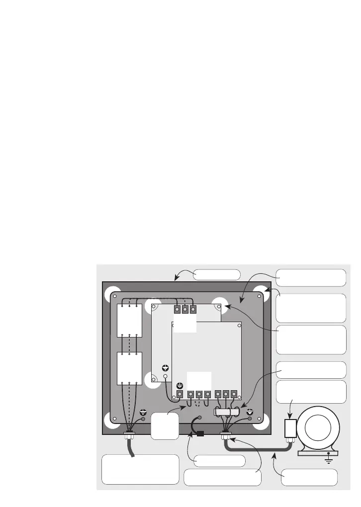
Main incoming supply
Earth terminating directly to
Back Plate as close to gland
as possible
UVW
M
Jaguar
VXS
Inverter
FP
Filter
LINE
Contactor
Fused
Switch
Remove paint from beneath
Back Plate mountings (4)
and ensure a sound
metal-to-metal contact
Short, thick link
Steel or aluminium Back
Plate (earth plane)
Remove paint from Back
Plate beneath FP Filter
mountings (4) and prevent
corrosion
Connect screen/armour and
earth conductor to local
earth here
Ferrite choke (2 turns)
Install close to inverter
Brass compression gland —
360
o
termination of screen
3c/4c motor cable,
screened/armoured
Steel enclosure
From FP
Filter
LOAD
terminals
L1
or
L
L3
or
N
L2
or
—
L1
or
L
L3
or
N
L2
or
—