Home
IMO Precision Controls
Controller
K7 Series
Page 183
IMO Precision Controls K7 Series - Page 183
235 pages
Manual
Save Page as PDF
To Next Page
To Next Page
To Previous Page
To Previous Page
Loading...
Chapter 8 Communication Function
8-60
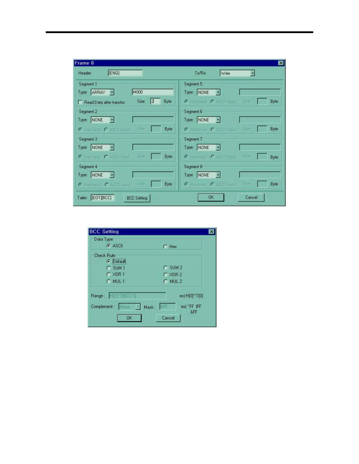
Designate the header,
segment, send/
receive , tail as above and then click the BCC Setting
Designate BCC Setting as above.
Click the OK button, and then you can see the
frame list
window
which is designated
182
184
Table of Contents
Main Page
default chapter
2
Table of Contents
2
Features
8
Terminology
10
Chapter 2. System Configuration 2-1~2-6
12
Overall Configuration
12
Basic System
12
Cnet I/F System
13
Product Functional Model
15
Product Function Block
15
Chapter 3. GENERAL SPECIFICATION
18
General Specifications
18
Chapter 4. Names of Parts 4-1~4-4
19
Base Unit
19
20-Point Basic Unit
20
30-Points Basic Unit
21
Expansion Module
22
Digital I/O Module
22
A/D D/A Combination Module
22
Analogue Timer Module
22
Chapter 5. CPU
23
Specifications
23
Operation Processing
25
Operation Processing Method
25
Operation Processing at Momentary Power Failure Occurrence
26
Scan Time
27
Scan-Watchdog Timer
27
Timer Processing
28
Counter Processing
31
Program
33
Error Handling
36
Operation Modes
37
RUN Mode
37
STOP Mode
38
PAUSE Mode
38
DEBUG Mode
38
Operation Mode Change
39
Functions
41
Self-Diagnosis
41
I/O Force On/Off Function
42
Direct I/O Operation Function
45
Memory Configuration
46
I/O No. Allocation Method
47
Built-In Flash Memory
48
Structure
48
Usage
49
External Memory Module
51
Structure
51
Usage
51
Battery
53
Chapter 6 Input and Output Modules
54
Input and Output Specifications
54
Digital Input Specifications
55
Base Unit
55
Digital Output Specifications
60
Base Unit
60
Chapter 7. Usage of Various Functions 7-1~7-60
64
Built-In Function
64
High-Speed Counter Function
64
Pulse Output Function
74
Pulse Catch Function
86
Input Filter Function
88
PID Control Function
89
External Interrupt Function
111
Special Module
113
A/D D/A Combination
113
Chapter 8. Communication Function 8-1~8-115
124
Introduction
124
System Configuration Method
125
Frame Structure
128
List of Commands
130
Data Type
131
Execution of Commands
132
1:1 Built-In Communication between GM7' S
154
Error Codes
168
User Defined Protocol Communication
170
Introduction
170
Parameter Setting
171
Example of Use
181
Chapter 8. Installation and Wiring
201
Installation
201
Installation Environment
201
Handling Instructions
204
Connection of Expansion Module
207
Wiring
208
Power Supply Wiring
208
Grounding
210
Cable Specifications for Wiring
211
Chapter 10 Maintenance 10-1~10-2
212
Maintenance and Inspection
212
Daily Inspection
212
Periodic Inspection
213
Chapter 11 Trouble Shooting 11-1~11-13
214
Basic Procedures of Troubleshooting
214
Troubleshooting
214
Troubleshooting Flowchart Used When the POWER LED Turns off
215
Troubleshooting Flowchart Used When the Error LED Is Flickering
216
Troubleshooting Flowchart Used When the RUN LED Turns off
217
Troubleshooting Questionnaire
221
Related product manuals
IMO Precision Controls K7M-DR30S
235 pages