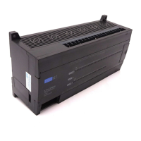
Chapter 4. Names of Parts
4
-
ై
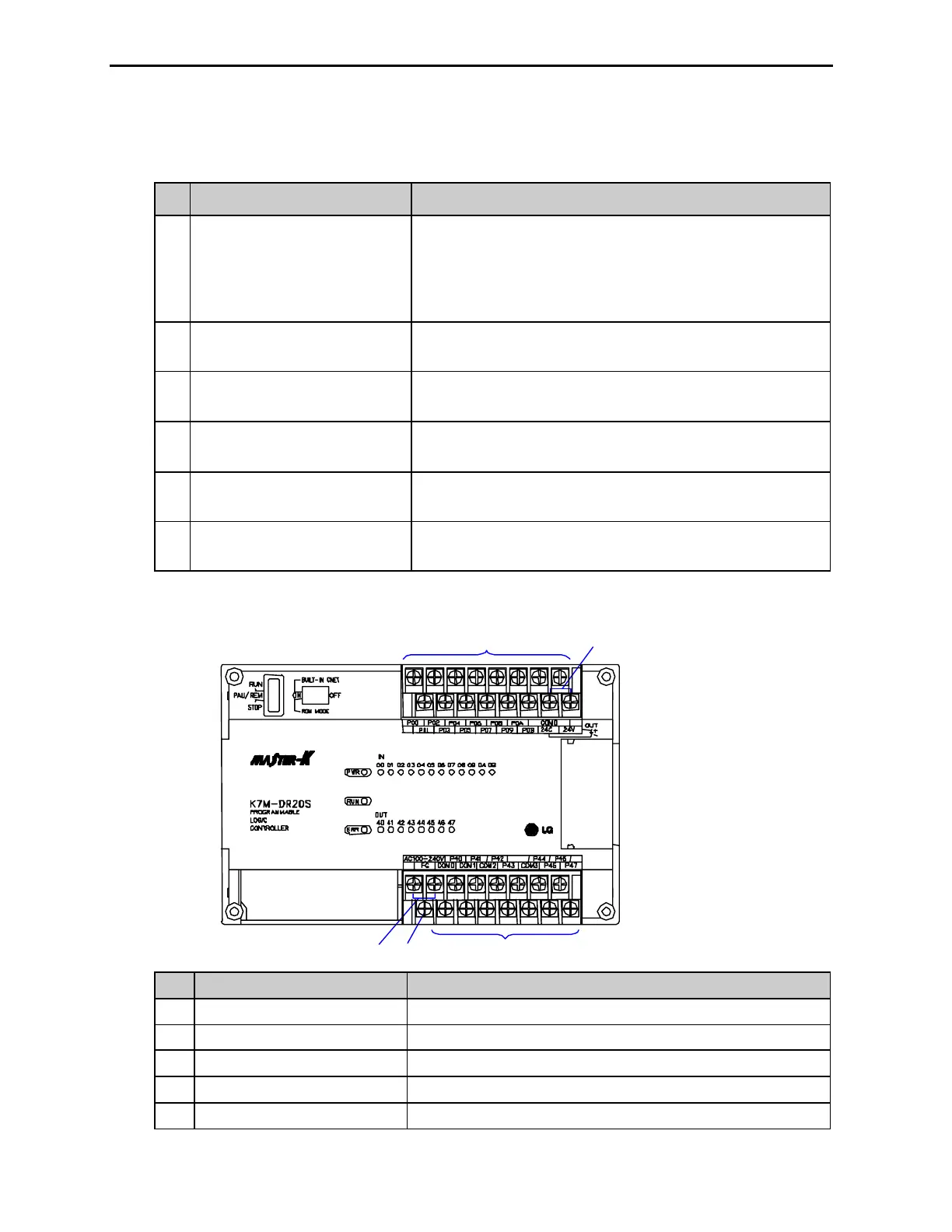
No Name
4 Key switch mode creation
Indicates base units drive mode
RUN: Indicates program operation
STOP: Stopped program operation
PAU / REM: usage of each modules are as follows:
ሪ
PAUSE : temporary stopping program operation
ሪ
REMOTE : Indicates remote drive
5 Dip-switch memory operation See Chapter 5
6 RS-232C connector 9-pin DIN connector to connect with external devices like KGLWIN
7
Expansion connector cover Connector cover to connect with expansion unit
8 Terminal block cover Protection cover for wiring of terminal block
9 Private hook DIN rail Private part hook for DIN rail
4.1.1 20-point base unit
No. Name Usage
1 Terminal block for power supply Terminal blocks for power supply (AC 100V ~ 240V)
2 FG circuit Frame ground
3 Output terminal Output connecting terminal
4 Input terminal Output connecting terminal
5 DC24V, 24G output terminal Service power supply for DC 24V needed place
① ② ③
④ ⑤