Chapter 8 Communication Function
8-74
8.3.4 Instruction and example
1) MODBUS
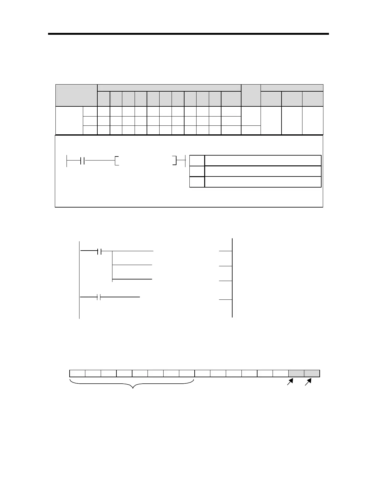
Available Device Flag
Instruction
M P K L
F
T C S D
#
D integer
Step
no.
Error
(F110)
Zero
(F111)
Carry
(F112)
S1OOOOOOO OO
S2OOOO OO OO
7
MODBUS
S3OOOO OO OO
O
Example program
S3 format is as below.
bit 15 bit 8 bit 1 bit 0
NDR : when the communication ends normally, this bit turns on during 1 scan.
Error bit : when communication error occurs, this bit turns on during 1 scan. At that time error code stores bit 8 ~ bit 15.
MODBUS S1 S2 S3 S1
Device address which is registered communication parameter
Device address which is stored communication data
S3
Device address which is displayed communication status
S2
[ MOV h0025 D0002 ]
[ MOV h0013 D0001 ]
[ MOV h0301 D0000 ]
[ MODBUS D0000 D1000 M100 ]
M0020
F0012
It designates slave station no. and function code.
It designates no. of reading
M0020 turns on, MODBUS communication starts .
Receive data stores D1000.
M100 stores communication status
It designates address
Error bit NDR bit
Error code