Chapter 11. Troubleshooting
11-
5
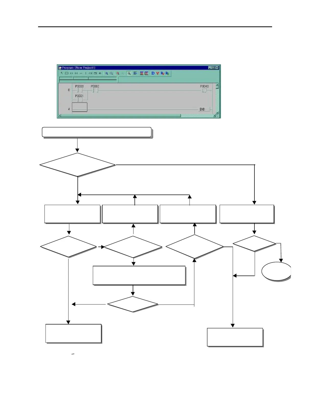
11.2.4 Troubleshooting flowchart used when the I/O part doesn’ t operate normally.
The following flowchart explains corrective action procedure used when the I/O module doesn’ t operate normally.
When the I/O module doesn’ t work normally.
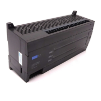
Check the status of P40 by
KGLWIN
Is the indicator LED of
the P40 on?
No
Replace the connector of the
terminal board
Measure the voltage of powe
supply in P40
Correct wiring.
Is the
voltage of power supply for load
applied?
Is the output
wiring correct?
Is the
terminal connector
connector appropriate?
Is it normal condition?
Separate the external wiring than check the condition of
output module.
Is it normal condition?
Check the status of P40
Replace the Unit
Continue
Yes
No
Yes
No
Yes
No
Yes
Yes
No
No
Yes