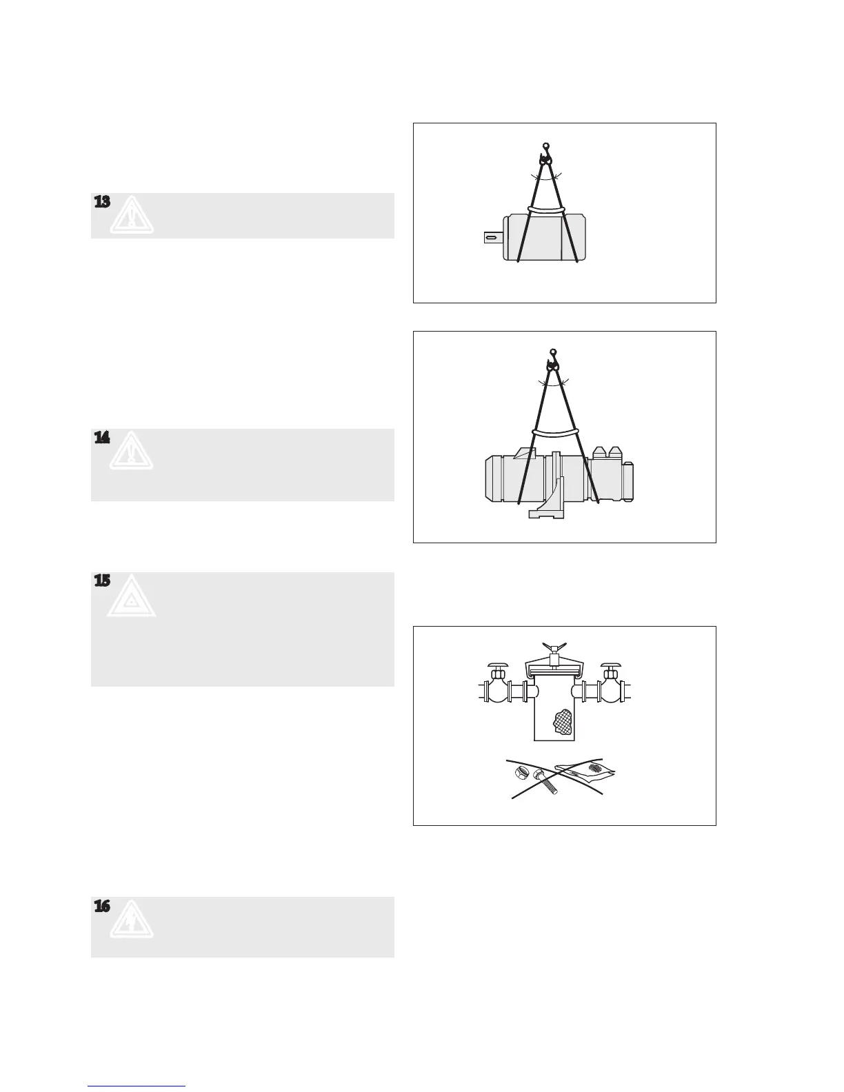
Fig 1. Liing the pump
Design limitations and technical data for each pump
are found in the Product description. Installation of
IMO AB low pressure pumps does not require special
skills. However, these instructions presume that the
work is carried out by experienced ers!
13
m
Failure to comply with these instructions
may cause damage and personal injury
Transport and storage
Always protect the pump against ingress of water and
other impurities. Store the pump in a clean, dry and
warm environment. The pump is delivered with the
internals oiled and with protective covers over the
pipe connections and drain openings. These covers
should remain in place for as long as possible during
the mounting and installation procedure but must be
removed before start up.
Lifting of pump
14
m
All pumps should be lied with straps
securely aached to the pump or pump
unit, so that the center of gravity is located
between the straps in order to avoid
tipping of the pump.
Liing of the complete pump unit with the liing
device aached to the motor, should be avoided as the
motor’s liing provisions may not be able to carry the
combined weight of the pump and motor.
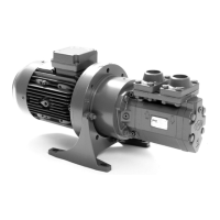
15
;
The installation must be designed
to minimize damage. Should an
operational or functional failure occur.
E.g. precautions should be considered to
collect oil spillage due to a broken pipe or
pump housing, to stop pump operation
if overheating should occur or if the oil
volume is below a minimum tank level.
Allignment and shaft couplings
The pump shall be connected to its driver via a exible
sha coupling; they may also be driven via gears or
pulleys as specied in the Product Description, pro-
vided that the radial forces are kept within the specied
range. An angular misalignment of 0.1° corresponds to
approximately. 0.2 mm deviation/100 mm. The coupling
and alignment shall be selected not to transmit any ax-
ial or radial loads on the sha ends. IMO AB standard
couplings shall have a distance between the coupling
halves as per table, g 4. The coupling halves shall be
secured by lock screws. For other types of couplings,
please refer to respective maker’s manual.
16
c
When ing the sha coupling, do not use
a hammer or similar as this may damage
the ball bearing and sha seal.
Use some kind of press tool.
Fig. 2 Strainer
Installation