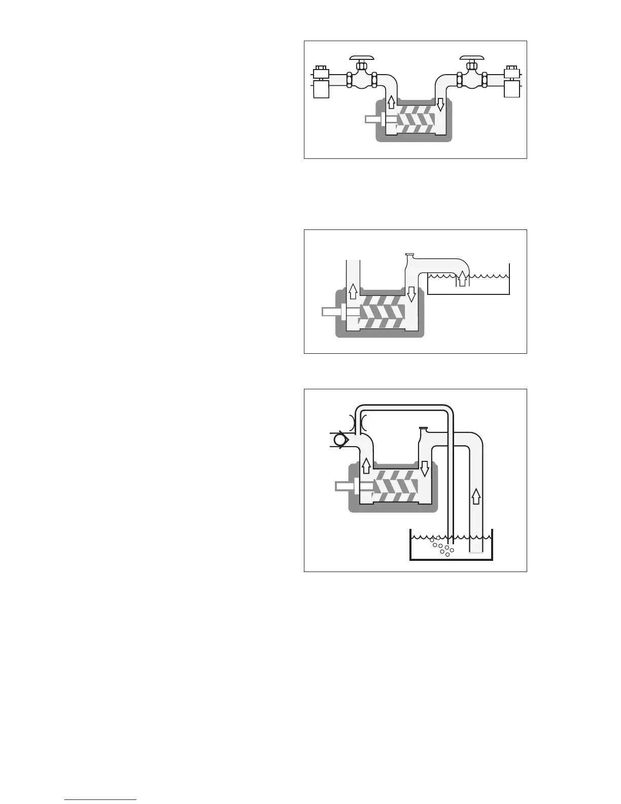
Fig. 7 Deaeration
Pipe connections
The pipe work shall be installed and supported so that
no pipe stresses are transferred to the pump body. The
pipe work should be tight in order to avoid leakage
and inltration of foreign particles and/or air. Shut o
valves should be installed in both suction and dis-
charge pipes, so that the pump can be hydraulically
isolated.
Suction line
The suction pipe should be designed so that the total
pressure drop, measured at the pump inlet ange, does
not exceed the suction capability of the pump. Make a
proper calculation of the suction line including com-
ponents such as valves, strainer, pipe bends etc. Gener-
ally, the pressure drop in the suction line should be as
low as possible, which is achieved if the suction pipe is
short, straight and has a suitable diameter. The veloc-
ity in the suction line should be kept in the range 0.5
- 1.2 m/s. For L.O. circulating systems, we recommend
to keep it as low as possible. The suction line must
be equipped with a port that allows lling the pump
before start.
Discharge line
The discharge line should be dimensioned to keep the
velocity in the range 1 - 3 m/s.
Deaeration
In installations with negative suction head, where the
pump might be started against a pressurized system, a
deaeration pipe with an orice (2-3 mm is recommend-
ed) has to be installed. The deaeration pipe should be
connected to the outlet pipe’s highest point. This must
also be installed when the pump is used as a stand-by
pump.
Shaft seal drain
The pump should be installed so that any leakage from
the sha seal does not become a hazard. As the sha
seal has to be lubricated a small amount of oil dripping
cannot be avoided. Provisions to collect the leakage
from the sha seal must be made. A drain pipe can
be connected to the drain connection on the pump.
However, when pumping heavy fuel oil or any other
liquid that is likely to become very viscous at ambient
temperature, we recommend that the liquid is allowed
to drop freely from the drain opening.
Liquid trap
In some mounting arrangements the pump may not
retain the liquid at stand still. In such installations the
suction pipe should be arranged so it forms a liquid
trap together with the pump, keeping the pump half
lled with liquid.
Fig. 5 Pipe connections
Fig. 6 Suction Line