2-16
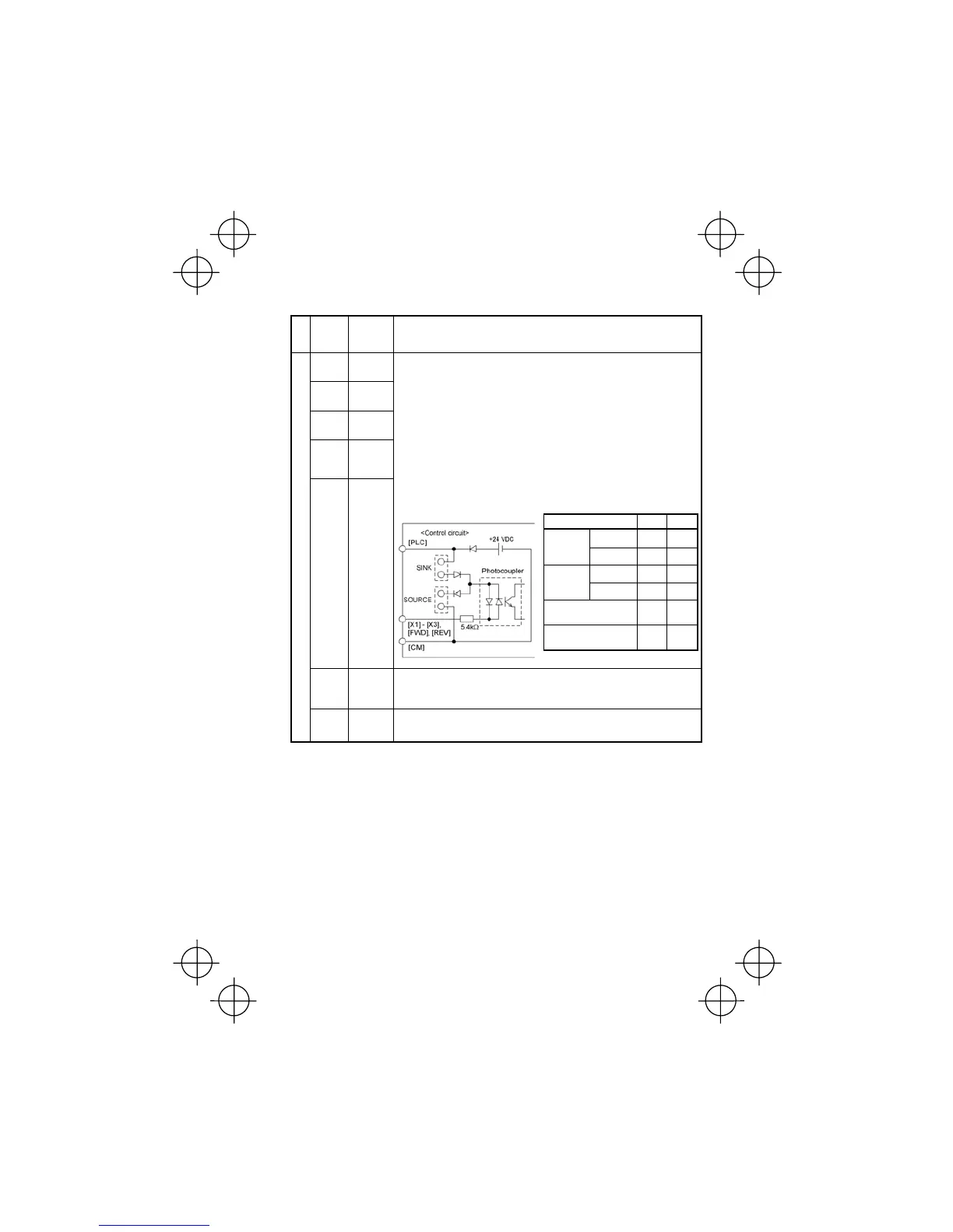
Item Min. Max.
ON level 0V 2V
Operation
voltage
(SINK)
OFF level 22V 27V
ON level 22V 27V
Operation
voltage
(SOURCE)
OFF level 0V 2V
Operation current at ON
(Input Voltage at 0 V)
2.5mA 5mA
Allowable leakage
current at OFF
- 0.5mA
Table 2.8 Continued
Classifi-
cation
Symbol Name Functions
[X1] Digital
input 1
[X2] Digital
input 2
[X3] Digital
input 3
[FWD] Forward
operation
command
[REV] Reverse
operation
command
(1) The various signals such as coast-to-stop, alarm from external equip-
ment, and multistep frequency selection can be assigned to terminals
[X1] to [X3], [FWD] and [REV] by setting function codes E01 to E03, E98,
and E99. For details, refer to Chapter 5, Section 5.2 "Overview of
Function Codes."
(2) Input mode, i.e. Sink/Source, is changeable by using the internal jumper
switch.
(3) Switches the logic value (1/0) for ON/OFF of the terminals between [X1]
to [X3], [FWD] or [REV], and [CM]. If the logic value for ON between [X1]
and [CM] is 1 in the normal logic system, for example, OFF is 1 in the
negative logic system and vice versa.
(4) The negative logic signaling cannot be applicable to [FWD] and [REV].
Digital input circuit specifications
[PLC] PLC
signal
power
Connects to PLC output signal power supply. (Rated voltage: +24 VDC,
Maximum output current: 50 mA)
Digital input
[CM] Digital
common
Common terminal for digital input signals
This terminal is electrically isolated from terminals [11] and [Y1E].