99903514:TELESCOPIC CRANE: 4-16
SECTION 4: INSTALLATION
4.14 MODEL 7020 CRANE INSTALLA-
TION
MINIMUM CHASSIS SPECIFICATIONS
BODY STYLE Conventional
Cab
WHEELBASE 189”
CAB TO AXLE 120”
FRAME SECTION MODULUS 19.2 in³
RBM 900,000 in-lb
FRONT AXLE RATING 11,000 lb
REAR AXLE RATING 21,000 lb
TRANSMISSION 5-speed
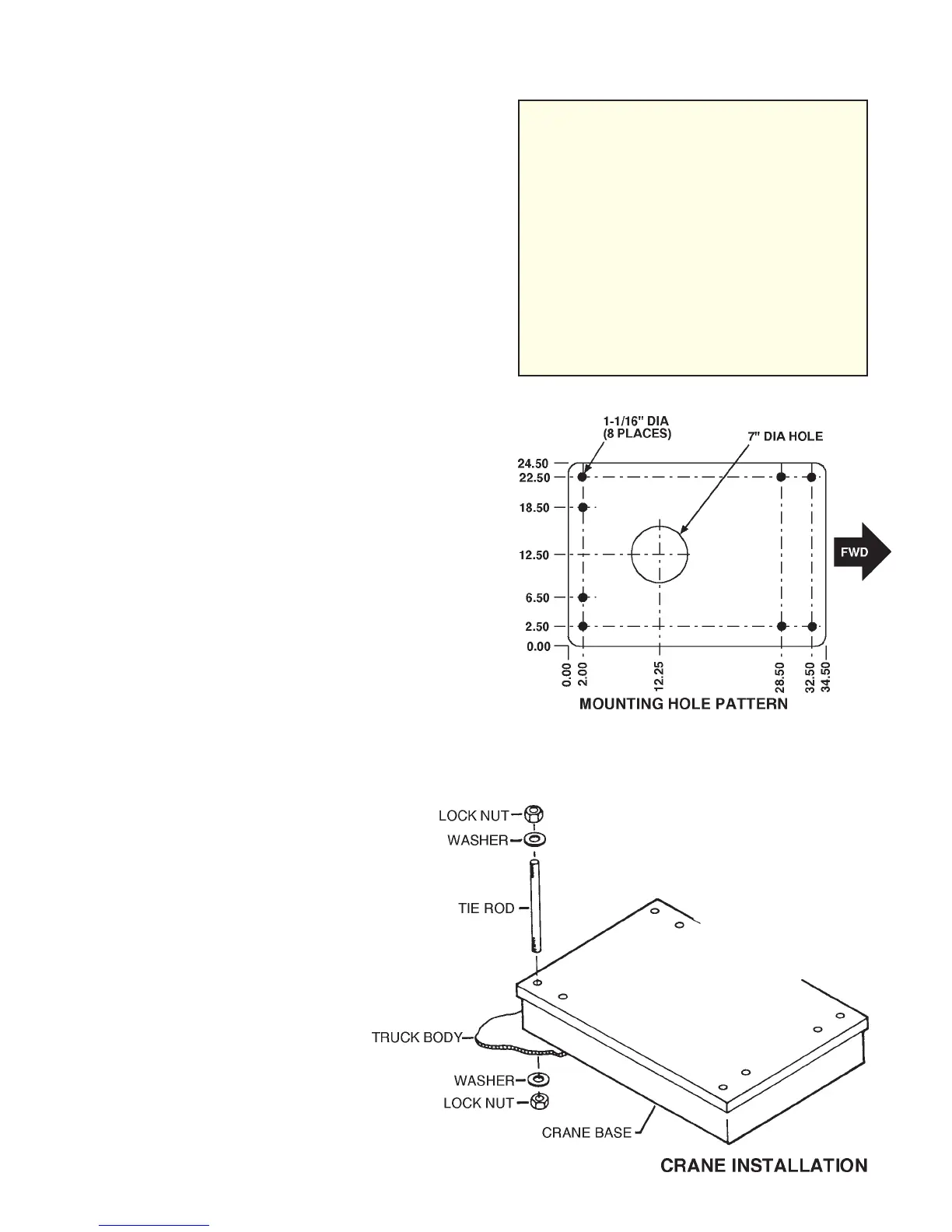
CRANE INSTALLATION
Install the 7020 crane only on an IMT-designed
and approved truck body. The body must be
designed to sustain the forces imposed by the
crane when lifting the full rated load. Before
attempting to install the crane, first install the
truck body.
To install the crane:
1. Use a lifting device capable of lifting the
weight of the crane, 2960 lbs. (1343kg.). Lift
the crane and move the carrier vehicle with
body installed under the crane. Lower the
crane into position on the body.
2. Install the mounting tie rods, washers, and
nuts to secure the crane base to the truck
body . Tighten and torque to 200 ft- lbs. (28
kg-m).
CAUTION
DO NOT ATTEMPT TO APPLY THE
SAME TORQUE TO THE SELF LOCKING
NUTS AND TIE RODS AS SHOWN IN
THE TORQUE DATA CHART. DO NOT
EXCEED 200 FT-LBS. EXCEEDING THE
STATED TORQUE OF 200 FT-LBS. (28
KG-M) MAY DAMAGE EITHER THE
CRANE BASE OR THE BODY.
POWER WRENCHING OF THE NUT IS
NOT RECOMMENDED UNTIL THE LEAD
THREAD OF THE NUT INSERT IS EN-
GAGED BY HAND TURNING.
20030115