99903514:TELESCOPIC CRANE:
2-5 SECTION 2: MAINTENANCE
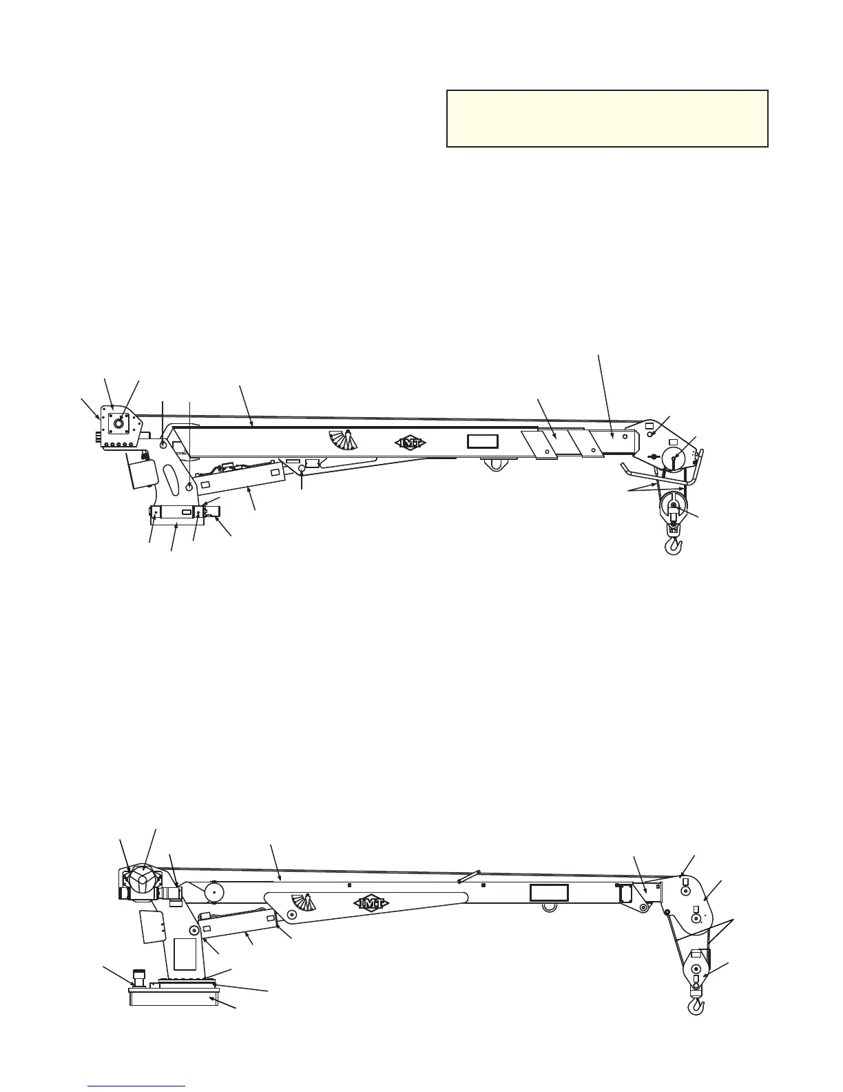
Figure B-7: Component & Grease Zerk
Locations - Models 7020 & 7025
1. Drive Gear
2. Turntable Bearing Grease Extension (Rotate
crane while greasing)
3. Pinion Gear
4. Lower Cylinder - Base End
5. Mast/Lower Boom Hinge Pin
6. Lower Cylinder - Rod End
7. Upper Sheave Pin
8. Lower Sheave Pin
9. Snatch Block Pin
10. Winch Outboard Bearing
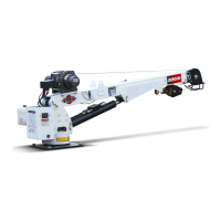
Figure B-6: Component & Grease Zerk
Locations - Models 5525, 6025, 6625
1. Turntable Bearing Grease Extension (Rotate
crane while greasing)
2. Worm Gear (Forward)
3. Worm Gear (Rear)
4. Lower Cylinder Base
5. Mast/Lower Boom Hinge Pin
6. Lower Cylinder Rod
7. Upper Sheave Pin
8. Lower Sheave Pin
9. Snatch Block Pin
10. Winch Bearing
Snatch
Block, 9
Wire
Rope
1st Stage
Extension Boom
(Manual or Hydraulic)
2nd Stage
Extension Boom
(Manual or Hydraulic)
Lower Boom
Extension
Cylinder
Rotation
Motor
Base
Winch
Mast
8
7
2
3
1
6
54
10
1,2
3
4
6
5
7
8
Snatch
Block,
9
Winch, 10
Rotation
Motor
Lower
Cylinder
Lower Boom
Wire
Rope
Mast
Base
1st Stage Ext. Boom
(Manual or Hydraulic)
MODELS 5525, 6025, & 6625
MODELS 7020 & 7025
NOTE
COMPONENTS ON CRANE DIAGRAMS
ARE IDENTIFIED BY NAME; GREASE
ZERKS ARE IDENTIFIED BY NUMBER.
20030115