99903514:TELESCOPIC CRANE: 3-5 SECTION 3: REPAIR
5. Install and tighten remaining bolts in the
correct sequence with the correct torque,
using the torque chart and the torque se-
quence in the General Reference section of
this manual.
3-9-3: WORM END PLAY & BACKLASH -
INTEGRAL BASE & WORM DRIVE (3020,
3820, 5020, 5525, 6025, 6625)
Crane models 3020, 3820, 5020, 5525, 6025,
6625 have an integral base and worm drive
rotation system.
To set both Worm End Play and Backlash, you
must locate the high tooth on the gear. Usually
this spot is marked by the manufacturer with
light blue paint. If you cannot find the paint
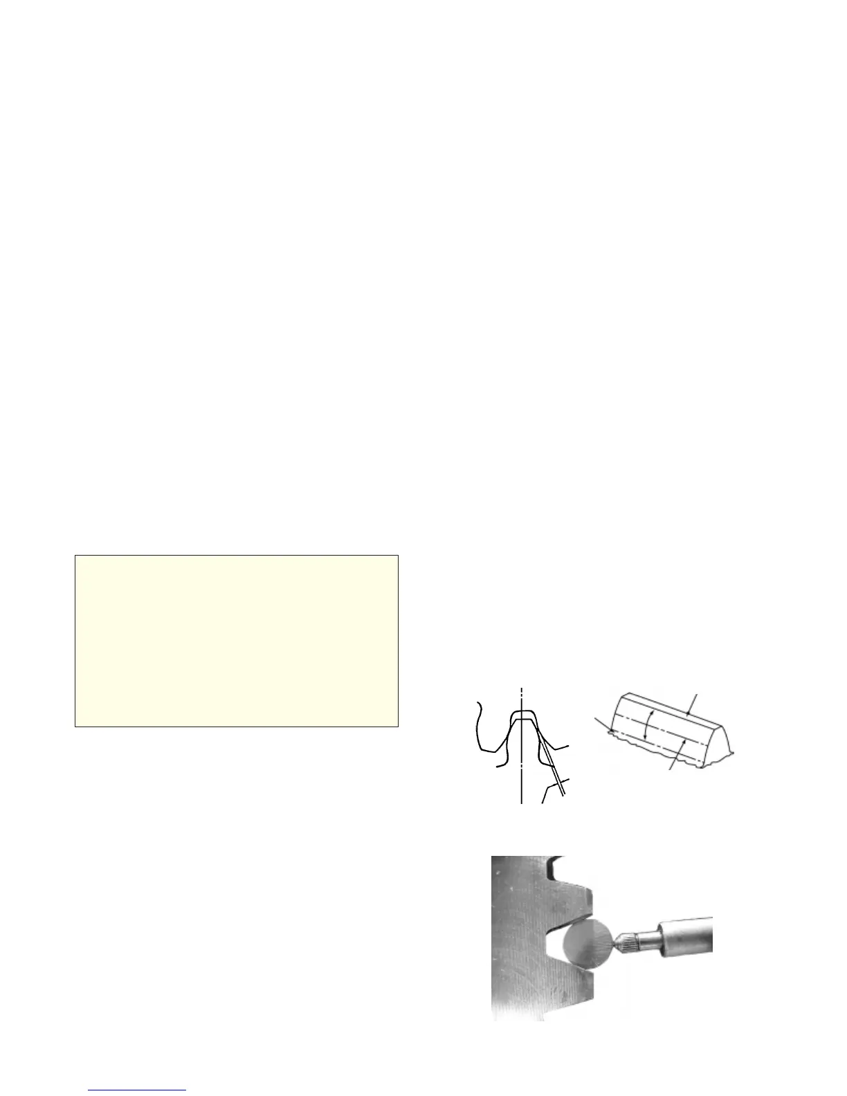
mark, identify the high tooth using a dial indica-
tor with a magnetic base and a round steel pin
which is large enough to contact the bearing
near the pitch line of the bearing tooth. Set the
indicator base on the face of the bearing race
that does not have teeth. Place the pin between
two of the teeth. Set the indicator probe on the
pin and adjust the dial to zero. Rotate the
bearing, checking every third tooth until you find
the highest indicator reading. Check three teeth
in both directions in this area to determine the
highest tooth. The amount of run-out varies
depending on the diameter of the bearing. Once
you find the high tooth, mark it for future refer-
ence.
3-9-1: REMOVING THE CRANE ROTA-
TION SYSTEM
1. Retract extension booms, and support both
the crane and mast fully.
2. Lower the boom so that the boom tip is as
low as possible.
3. Cinch two slings or a hoist on opposite
sides of the boom center of gravity. Hook
slings on hoist and raise hoist to tension the
slings.
4. Identify, mark, and remove hose connection
between the crane base and boom. Cap or
plug all open hydraulic fittings.
5. With boom fully supported, remove and
discard bolts which secure mast to rotation
system. Upon reassembly, replace bolts
with new, properly-torqued bolts.
6. Remove rotation system from mounting
system.
3-9-2: SETTING BACKLASH - IMT BASE
& WORM DRIVE (1007, 1015, 2020)
NOTE
BACKLASH IS DEFINED AS THE SHORTEST
DISTANCE BETWEEN NON-DRIVING TOOTH
SURFACES OF ADJACENT TEETH IN MATING
GEARS. BACKLASH IS MEASURED AT THE
HIGH SPOT ON THE TURNTABLE BEARING
(USUALLY INDICATED BY YELLOW OR LIGHT
BLUE PAINT), USING A THICKNESS OR
FEELER GAUGE AT OR NEAR THE PITCH
DIAMETER AND TANGENT TO THE GEAR
TEETH.
Telescopic crane models 1007, 1015, and 2020
have a common gear and rotation system. To
set the backlash on these models,
1. Bolt the worm gear in place.
2. Position the high spot on the bearing next to
the center of the worm gear. (The high spot
on the bearing is marked by the manufac-
turer with paint.)
3. Screw a bolt into the threaded hole nearest
the high tooth. Screw additional bolts into
threaded holes at 90° from the high tooth.
4. Check for clearance between gears using a
feeler gauge. Clearance should be between
.005 and .012”. Rotate the gear completely
to verify that the assembly does not bind.
BACKLASH
ROOT
FILLET
PITCHLINE
TOPLAND
Figure C-3: Bearing Tooth Contact Point
Figure C-4: Pin and Indicator Tip
20030115