99903514:TELESCOPIC CRANE: 3-6 SECTION 3: REPAIR
To set the worm end play:
1. Locate the high tooth on the gear. (The high
spot on the bearing is marked by the manu-
facturer with paint.)
2. Screw a bolt into the threaded hole nearest
the high tooth. Screw additional bolts into
threaded holes at 90° from the high tooth.
3. Mount a magnetic base with an indicator
attached on top of the worm housing and at
the opposite end from where the motor is
mounted.
4. Adjust the indicator to read from the end of
the worm shaft. Set the indicator to “0”.
5. Using two of the bolts as handles, rotate the
outer race back and forth. Read the total
indicator movement. The measurement is
the end play of the worm. The specification
for end play is +0.000/-0.004. If your end
play does not meet the specification, re-
move the bearing retainer and add or re-
move shims from the unit. Repeat the
measurement process until the end play
meets the specification.
To set the gear bearing backlash:
1. Locate the high tooth on the gear. (The high
spot on the bearing is marked by the manu-
facturer with paint.)
2. Rotate the bearing until the high tooth is
engaged with the worm. Loosen the three
bearing retaining allen head capscrews just
enough to be able to move the bearing
toward or away from the worm. Screw a
bolt into the threaded hole in the bearing
nearest the worm.
3. Set the magnetic indicator base on the
worm housing with the indicator probe
against the bolt, and set the indicator dial at
zero.
4. Move the bearing back and forth. Watch the
indicator dial, and adjust the bearing in or out
of the worm until the total indicator move-
ment is 0.005”. NOTE: Deduct any end play
inthe worm from the indicator reading.
5. Rotate the bearing 180°. Recheck the
backlash. Total backlash should be 0.005”
to 0.012”.
3-9-4: TURNTABLE GEAR REMOVAL &
REPLACEMENT (7020 & 7025)
Model 7020 and 7025 cranes are equipped with
a turntable gear. You can remove and replace
the entire gear assembly using a hoist, If a hoist
is not available, some boom disassembly will be
necessary.
1. Retract extension booms.
2. Operate LOWER and EXTENSION boom
control levers to position outer boom verti-
cally with the boom point as low as possible.
3. Place two fabric slings around the boom.
Cinch on opposite sides of the boom center
of gravity. Hook slings on hoist and raise
hoist to tension the slings.
4. Identify, mark and remove hose connections
between the crane base and boom. Cap or
plug all open hydraulic fittings.
5. With base, mast, and boom fully supported,
remove bolts which secure mast to turntable
gear.
CAUTION
DO NOT LIFT CRANE TOO QUICKLY.
HOSE DAMAGE MAY OCCUR.
7. Turntable gear bearing is now exposed.
Remove cap screws that secure turntable
gear to crane base.
8. Remove turntable gear from crane base.
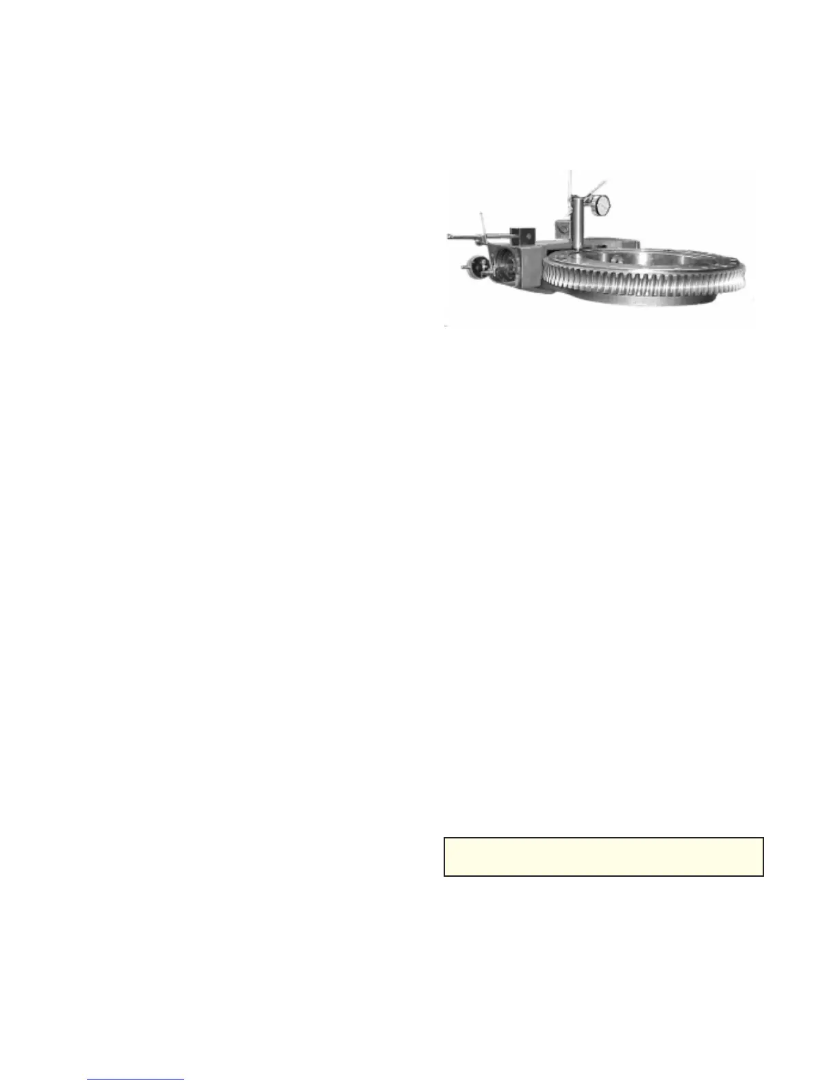
Figure C-5: Dial Indicator Set-up
6. After setting the backlash, torque the bearing
retaining allen head capscrews which
watching the indicator dial so that the cor-
rect backlash setting is maintained.
20030115