99903514:TELESCOPIC CRANE: 3-7 SECTION 3: REPAIR
9. Thoroughly clean the top of the crane base
and bottom of the new turntable gear bear-
ing. The mating surfaces must be clean
and dry - no oil or grease.
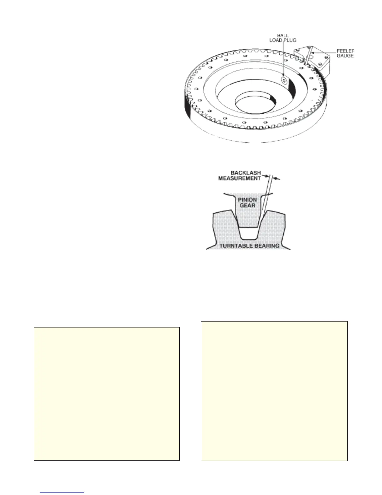
10. Install the new gear bearing, with ball loading
plug located next to pinion gear (See Figure
C-6), using new bolts, hardened flat wash-
ers and Loctite 262 or an equivalent thread
lock on bolt threads. Torque all cap screws
per Torque Data Charts in the general
reference section.
11. Reverse procedure for reassembly. Use
new cap screws and hardened washers
when attaching mast to turntable gear.
Torque cap screws per Torque Data Charts
in the general reference section.
12. Start the unit and slowly cycle all of the
controls to evacuate air trapped in the
hydraulic system. Simultaneously check for
leaks.
13. After air has been purged from the system,
check the reservoir oil level and top off oil if
necessary.
14. Lift the full rated load and swing it completely
around in both directions. Actuate the
controls very slowly and keep the load as
close to the ground as possible. Set the
load down and move the crane to the stored
position.
15. Recheck the gear bearing bolt torque of all
gear bearing mounting bolts.
Figure C-6: Turntable Gear Bearing
Installation
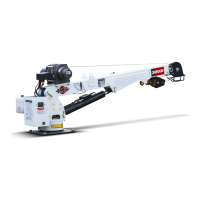
Figure C-7: Turntable Gear Bearing
Backlash Measurement
WARNING
AFTER REMOVAL, REPLACE ALL GEAR
BEARING MOUNTING BOLTS WITH IDEN-
TICAL, NEW BOLTS. FAILURE TO RE-
PLACE GEAR BEARING BOLTS MAY
RESULT IN BOLT FAILURE DUE TO
METAL FATIGUE AND COULD CAUSE A
SERIOUS INJURY OR DEATH.
BEFORE TORQUING, SEE TURNTABLE
BEARING FASTENER TIGHTENING SE-
QUENCE IN THE REFERENCE SECTION.
CHECK ALL BOLTS AFTER SWINGING
THE FULL RATED LOAD. APPLYING THE
FULL LOAD AGAINST ALL OF THE BOLTS
WILL TEST BOLT TORQUES.
NOTE
FOR PROPER OPERATION OF THE
CRANE, THE HIGH SPOT ON THE TURN-
TABLE GEAR MUST BE MATCHED TO
THE PINION GEAR. THE HIGH SPOT ON
THE TURNTABLE GEAR IS NORMALLY
MARKED WITH YELLOW OR LIGHT BLUE
PAINT. REMOVE PAINT AND CHECK
GEAR BACKLASH WITH A FEELER
GAUGE. CLEARANCE BETWEEN PINION
GEAR AND TURNTABLE GEAR BEARING
TEETH WILL USUALLY BE LISTED ON
THE BASE ASSEMBLY DRAWING IN THE
PARTS SECTION OF YOUR SPECIFIC
CRANE MANUAL. SHIFT THE TURN-
TABLE GEAR AROUND TO ADJUST THE
BACKLASH. SEE FIGURE C-7 FOR BACK-
LASH INFORMATION.
20030115