EasyManua.ls Logo

IMT CMD.CTRL - User Manual

IMT CMD.CTRL
175 pages
Print Icon
To Next Page IconTo Next Page
Loading...
IOWA MOLD TOOLING CO., INC.
P.O. Box 189
Garner, IA 50438
Tel: 641.923.3711
Fax: 641.923.2424
www.imt.com
Operators
Manual
Manual # 99906363
Revised 10-13-2022
Copyright © 2022 Iowa Mold Tooling Co., Inc.
All rights reserved
No part of this publication may be reproduced, stored in a retrieval system, or transmitted in any form or by any
means, electronic, mechanical, photocopying, recording or otherwise without the prior written permission of Iowa
Mold Tooling Co., Inc.
Iowa Mold Tooling Co., Inc. is an Oshkosh Corporation Company

Table of Contents

Question and Answer IconNeed help?

Do you have a question about the IMT CMD.CTRL and is the answer not in the manual?

Overview

This document serves as the Operator's Manual for the Iowa Mold Tooling Co., Inc. (IMT) CMD.CTRL system, identified by Manual #99906363, revised on October 13, 2022. The manual provides comprehensive instructions for operating and maintaining the associated vehicle and crane equipment.

Function Description:

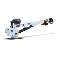
The CMD.CTRL system is a control interface designed to manage various functions of a service vehicle equipped with an IMT crane. It integrates controls for lights, stabilizers, crane operations, an Integrated Power Unit (IPU), and other vehicle functions. The system features a handheld body module with a display screen and keypad for user interaction, as well as a radio remote control for crane operations. The primary goal of the system is to provide a centralized and intuitive interface for operators to control complex machinery safely and efficiently.

Important Technical Specifications:

Handheld Remote (70735198):

  • Power:
    • Vin: +4.0 to +6.0 VDC
    • Batteries: Four "AA" cell
    • Battery Life: 30 hours
    • Low V Shutdown: 4.0 VDC
    • Auto-shutdown: 10 min. of button inactivity
  • Environment:
    • Operating Temp: –20° C to 55° C (–4° F to 131° F)
    • Storage Temp: –40° C to 55° C (–40° F to 131° F)
    • Humidity: 0 to 100%
  • Radio:
    • Frequency: 2405–2480 MHz
    • RF Power: 100 mW (max.)
    • License: None required
    • Modulation: DSSS
    • Antenna: Internal
  • Enclosure:
    • Dimensions: 230.6 x 133.9 x 146.9 mm (9.1 x 5.3 x 5.8 inches)
    • Total Weight: 2.2 lbs
    • Durability: High Impact Polymer case
    • Faceplate: Aluminum or Polycarbonate
  • Control Switches:
    • Toggle: Six 3-position spring return to center
    • Trigger: Spring release
    • Mushroom: Professional Stop
  • Display: LCD, 536 x 336 pixel resolution

Base Unit (70735199):

  • Power:
    • Vin: +9 to +36 VDC
  • Radio:
    • Frequency: 2405–2480MHz @ 100mW
    • License: None required
    • Modulation: Channel-Hopping Direct Sequence Spread Spectrum (CH DSSS)
    • Antenna: Internal
  • Environment:
    • Operating Temp: –20° C to 70° C (–4° F to 158° F)
    • Storage Temp: –40° C to 85° C (–40° F to 185° F)
    • Humidity: 0 to 100%
    • Vibration/Shock: IEC60068-2-6, 10 Hz to 150 Hz @ 1.0 g peak acceleration, 10.0 g peak shock acceleration
  • Indicators (5):
    • CAN 1 TX/RX: TX=red, RX=green; Flashes upon event
    • CAN 2 TX/RX: TX=red, RX=green; Flashes upon event
    • ERR/HLTH: Error= red, Health=green; blinks 1x/sec
    • RF TX/RX: TX=red, RX=green; Flashes upon event
    • POWER: Amber; solid when normal; Flashes upon event
  • Enclosure:
    • Dimensions: 119 mm x 133 mm x 36 mm (5.24” x 4.69” x 1.42”)
    • Durability: High Impact Polymer
    • Mounting Holes: 7.4 mm (0.29”) dia. 102 mm center-to-center (4” center-to-center)
  • Serial Parts: Two CAN, One RS-232

Usage Features:

  • Navigation: The system uses a menu-driven interface on the handheld body module. Operators navigate through menus using arrow buttons (left, right, up, down) and a "Select" button. A "Backspace" button allows returning to previous screens or the Main Menu.
  • Main Menu Options: The main menu provides access to:
    • Lights: Control various lighting groups (All, Compartment, Front, Rear, Left, Right, Boom Tips) and individual lights. The display shows a visual representation of selected lights turning yellow.
    • Stabilizers: Maneuver selected stabilizers in a two-step process, allowing individual control of rear left, rear right, and front stabilizers (extendable or non-extendable). Stabilizer control is disabled when the crane remote has the stabilizer screen selected.
    • Crane: Enable/disable crane power, PTO, boom tip lights, and access crane override and recovery functions. The system includes a confirmation step for stabilizer deployment before crane operation.
    • IPU (Integrated Power Unit): Activate the IPU for hydraulic power to crane and body functions. This involves engaging the E-Brake, turning the chassis ignition to "RUN," activating a cab switch, and waiting for the IPU to become operational.
    • Vehicle Functions: Control PTO, compressor, auxiliary outputs (AUX 1, AUX 2), horn, engine start/stop, and transmission inhibit override.
    • Diagnostics: View input/output states, fault codes (up to 25 most recent), hour meters (chassis, crane/IPU, compressor), stabilizer acknowledgements, crane overload events, and compartment fan tests.
    • Operator Settings: Configure lights (exit cab, reverse flood, search, auto boom tip), PTO activation, and auxiliary activation. Changes may require a power cycle.
    • Vehicle Configurations: Set up PIN, chassis type, transmission, PTO start delay, crane placement, stabilizers, compressor, master locks, searchlights, reverse lights, auxiliary E-Brakes, transmission inhibit alarm, RPM speed, compartment fans, crane model, hydraulic mode, remote control type, boom length sensor, boom angle sensor, crane tilt derate, boom lift max, boom telescope max, boom rotate max, and winch max. PIN entry is required for modifications.
    • Display Settings: Adjust language (English, Spanish, French), brightness, working sleep time, standby sleep time, and view system version information.
  • Radio Remote Control (70735198):
    • Power Up: Toggle the Right Fixed Function (RFF) toggle UP for 0.5 seconds.
    • Association: Process to connect the handheld remote to the base unit, requiring both units to be powered OFF initially.
    • Screen Order: Navigate through Crane, Stabilizer, Light, and Operation screens using the RFF toggle DOWN.
    • Crane Mode: Control crane rotation (CCW/CW), boom extension (retract/extend), winch (down/up), and boom lift (down/up) using soft toggles. Displays LMI, boom angle, truck tilt, weight, and horizontal distance.
    • Stabilizer Screen: Control individual stabilizers (rear left, rear right) for UP/DOWN and EXTEND/RETRACT functions using soft toggles.
    • Light Screen: Control various body lights (All, Boom Tip, Left/Right Side Floods, Front/Rear Floods, Left/Right Compartment Lights) using soft toggles.
    • Compressor Activation: Turn the compressor ON/OFF using the LFF toggle UP. Compressor runs when air tank pressure is below set point.
    • Engine Speed Control: Adjust RPM HI/LO using the LFF toggle DOWN.
    • Emergency Stop: Mushroom button for immediate machine stop.
    • Trigger: Controls crane movement speed.

Maintenance Features:

  • Battery Installation/Replacement: Detailed instructions for replacing the four "AA" cell batteries in the handheld remote, emphasizing correct polarity and ensuring the O-Ring is intact.
  • Diagnostic Tools: The system provides extensive diagnostic capabilities, including:
    • Fault Codes: Displays 25 most recent fault codes in chronological order, with descriptions and triggers. Faults can be cleared from the log.
    • Hour Meters: Tracks operating hours for the chassis, crane (or IPU), and compressor, up to maximum limits.
    • Input/Output States: Allows monitoring the active status of various inputs and outputs, indicated by green circles.
    • Compartment Fan Test: Activates compartment fans for 20 seconds to verify functionality.
  • Troubleshooting: The manual includes fault tables for both body and crane codes, providing help messages, DTCs, stop/warn icons, actions, triggers, and latch status to assist operators in identifying and resolving issues.
  • PIN Setup: Vehicle configuration settings are protected by a 4-digit PIN, which can be obtained from IMT Technical Support by providing the Body Module Serial Number.
  • Software Version Information: The "About System" menu in Display Settings provides software version and serial number details for the Display, Body Module, Crane Module, and Remote IO Module.

IMT CMD.CTRL Specifications

General IconGeneral
BrandIMT
ModelCMD.CTRL
CategoryConstruction Equipment
LanguageEnglish

Related product manuals