5
NCSP35CM
It’s a good idea to read all of the instructions before beginning the
installation. We recommend having your NCSP35CM installed
by a reputable RV dealership
• Tools and Supplies
You will need these tools and supplies to install your NCSP35CM :
• Phillips screwdriver
• #2 square drive bit
• Wire cutters and strippers
• Electrical tape
• Volt meter/test light
• Crimping tool
• Fork Crimp connectors
• Minimum of 24 gauge wire required to connect DC to BCM
• 10 gauge wire for power and slide connections
• 14 and 18 gauge wire for all other connections
• Four #8 PH (0.164” x 0.75”) screws for the DC
• Six #8 PH (0.164” x 1.0”) screws for the BCM
• Disconnecting the Battery
To prevent a short circuit, be sure to turn off 12V power and remove
the negative (-) battery cable prior to installation.
• Selecting the Mounting Location
Select a mounting location, taking care to avoid the following:
• Places exposed to heat-radiating appliances such as electric heaters
• Adjacent to other equipment that radiates heat
• Under thermostats
• Poorly-ventilated or dusty places
• Moist or humid locations
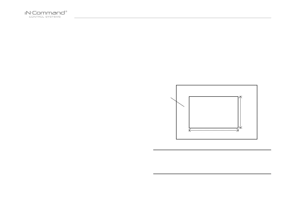
CUTOUT FOR DISPLAY COMMANDER (DC)
NOTE: Before cutting the mounting hole, make sure the area
behind the mounting location is clear of wires, fuel and vacuum
or water lines; ensure there is at least a 2.75”clearance below
the Display Commander to allow for programming by USB stick.
RECOMMENDED CUTOUT
WALL FOR
REFERENCE
CUTOUT
4 11/16"
7 1/4"
• Mounting the Display Commander (DC)
• Use the mounting hole diagram to measure and cut a mounting hole,
allowing space below for future programming and behind for ventilation
• Route power and transmit wires through the hole and connect
• Check and ensure correct operation
• Mount the unit using four #8 PH (0.164” x 0.75”) screws
• Attach Trim ring
• INSTALLATION