sealing compound.
with Natural Gas.
pressure setting.
GAS CONNECTION (CONTINUED)
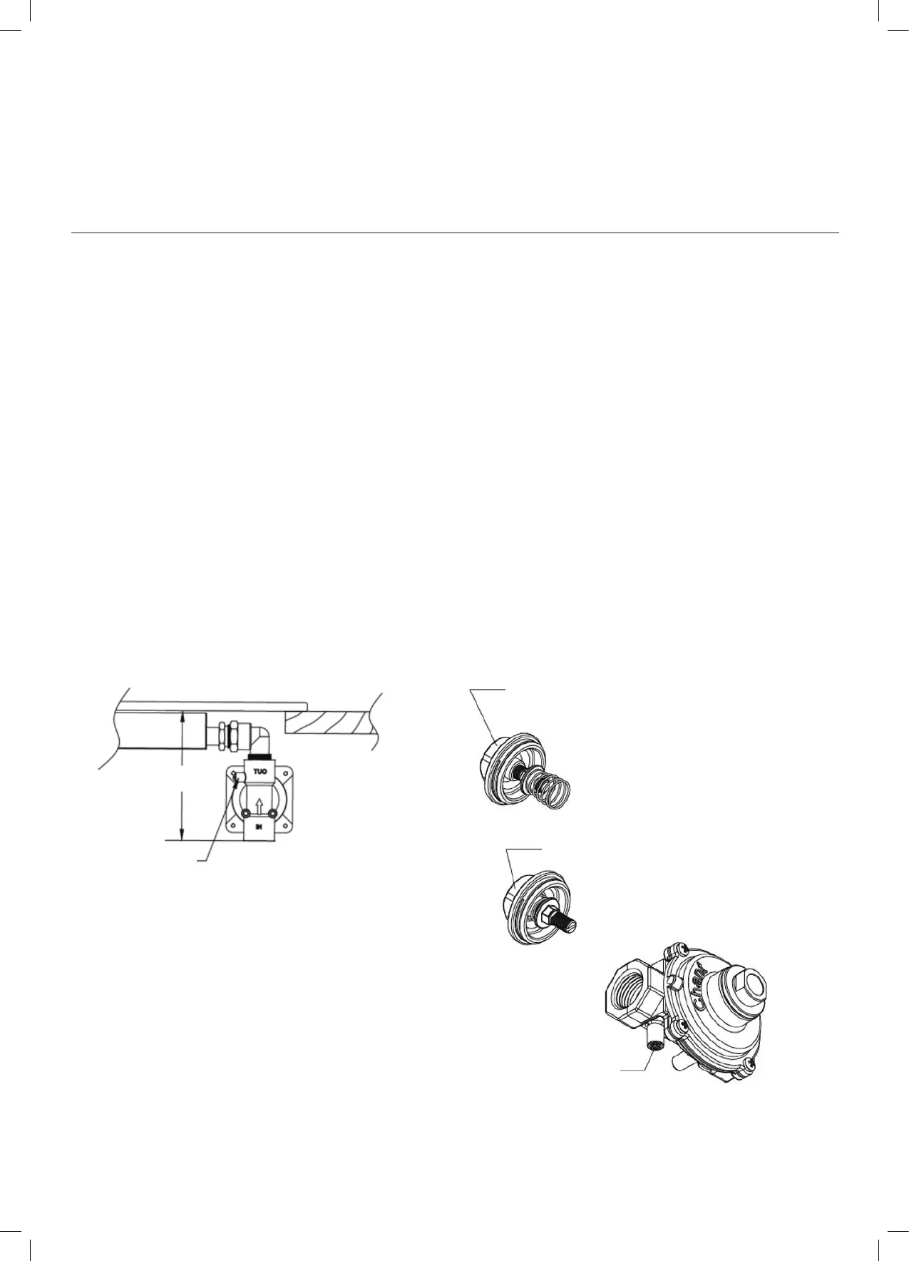
Assembly of the regulator
The assembly of the regulator to the cooktop manifold is
achieved via the elbow union and sealing washer supplied,
refer to figure 9.
The ½” parallel thread connects to the manifold, and the
sealing washer is placed between the manifold end and
the flat face on the elbow.
The ½” tapered thread connects to the outlet of
the regulator, and is sealed on the thread using approved
thread sealing tape or approved thread sealing compound.
The inlet of the regulator is a ½” parallel thread and
is connected to consumer piping or hose assembly.
Regulators are supplied pre-adjusted and configured
by the component maker for use with Natural Gas.
The appliance installer is not required to make an
adjustment to obtain the correct outlet pressure setting.
An arrow on the base of the regulator indicates the
direction of gas flow when the inlet and outlet of the
regulator is orientated correctly. When the regulator has
been fitted check for leaks from the connections with
soapy water.
Figure 9
CHECKING THE GAS SUPPLY
1.
Check the manometer zero point is correct.
2.
Connect the manometer to the cooktop pressure point.
This is located on the regulator.
3.
Turn on the gas supply and electricity and try to
ignite the gas.
NOTE! It will take additional time to light the gas for the first
time as air needs to be purged from the pipes.
4.
With the appliance operating check the outlet pressure
•
when all burners of the appliance are operating
at maximum,
•
when the smallest burner of the appliance is
operating at minimum.
Under these conditions the outlet pressure should not
vary from the nominal outlet pressure of 1.00kPa by
more than ±0.20kPa.
If the regulator appears to not be performing satisfactorily,
then check the following points:
1.
If the outlet pressure is consistently too low then the inlet
pressure may be too low and adjustment of an upstream
regulator may be needed, or an upstream regulator or
valve with insufficient flow capacity may be present in
the gas supply line. If this is suspected then it may be
necessary to repeat the checks whilst measuring both
the inlet and outlet pressure to determine if the inlet
pressure is in the range 1.13 – 5kPa.
2.
Check that the regulator has been fitted to the gas
supply line in the correct orientation, the arrow on the
base of the body indicates the direction of gas flow.
Once these checks have been completed, if the
regulator still fails to perform in a satisfactory manner it should
be replaced.
Table 3
 Loading...