tina03e1 (0206) BPG400 v1.om 17
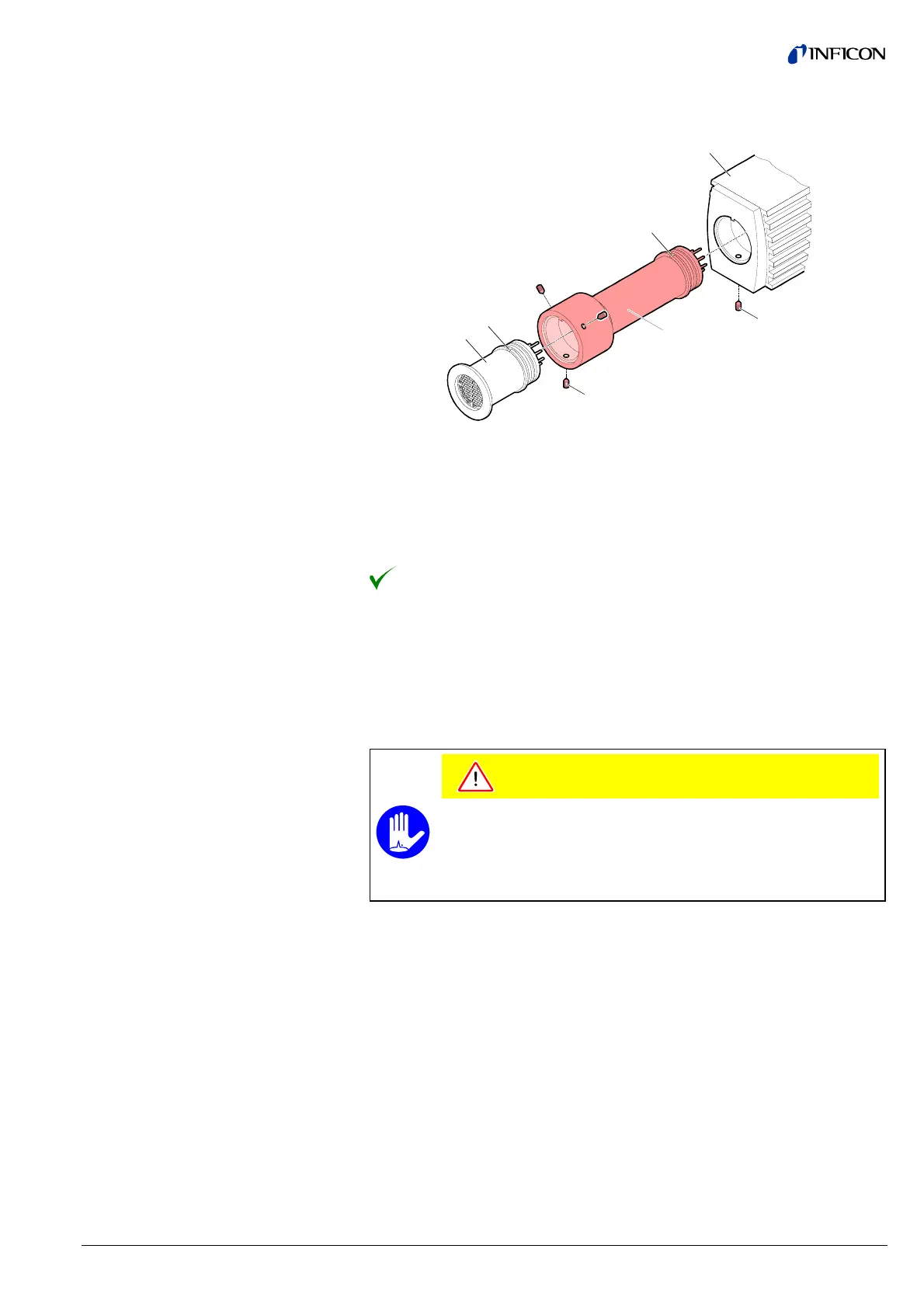
Secure the sensor with the hex socket set screws (7) using an Allen key,
size 1.5 mm.
6
7
3
4
4a
2
1
Slide the electronics unit (2) in to the mechanical stop (be careful to cor-
rectly align the pins and notch (4a)).
Secure the electronics unit (2) with the hex socket set screw (1) using an
Allen key, size 2.5 mm.
The extension is now installed.
In severely contaminating processes and to protect measurement electrodes opti-
cally against light and fast particles, replacement of the built-in grid by the optional
baffle (® 2 47) is recommended.
The optional baffle will be installed at the sensor opening of the deinstalled gauge
(Deinstallation ® 2 40).
Caution
Caution: dirt sensitive area
Touching the product or parts thereof with bare hands increases the
desorption rate.
Always wear clean, lint-free gloves and use clean tools when working
in this area.
· Baffle (® 2 47)
· Pointed tweezers
· Pin (e.g. pencil)
3.1.3 Using the Optional Baffle
3.1.3.1 Installing the Baffle
Required tools / material