tina03e1 (0206) BPG400 v1.om 25
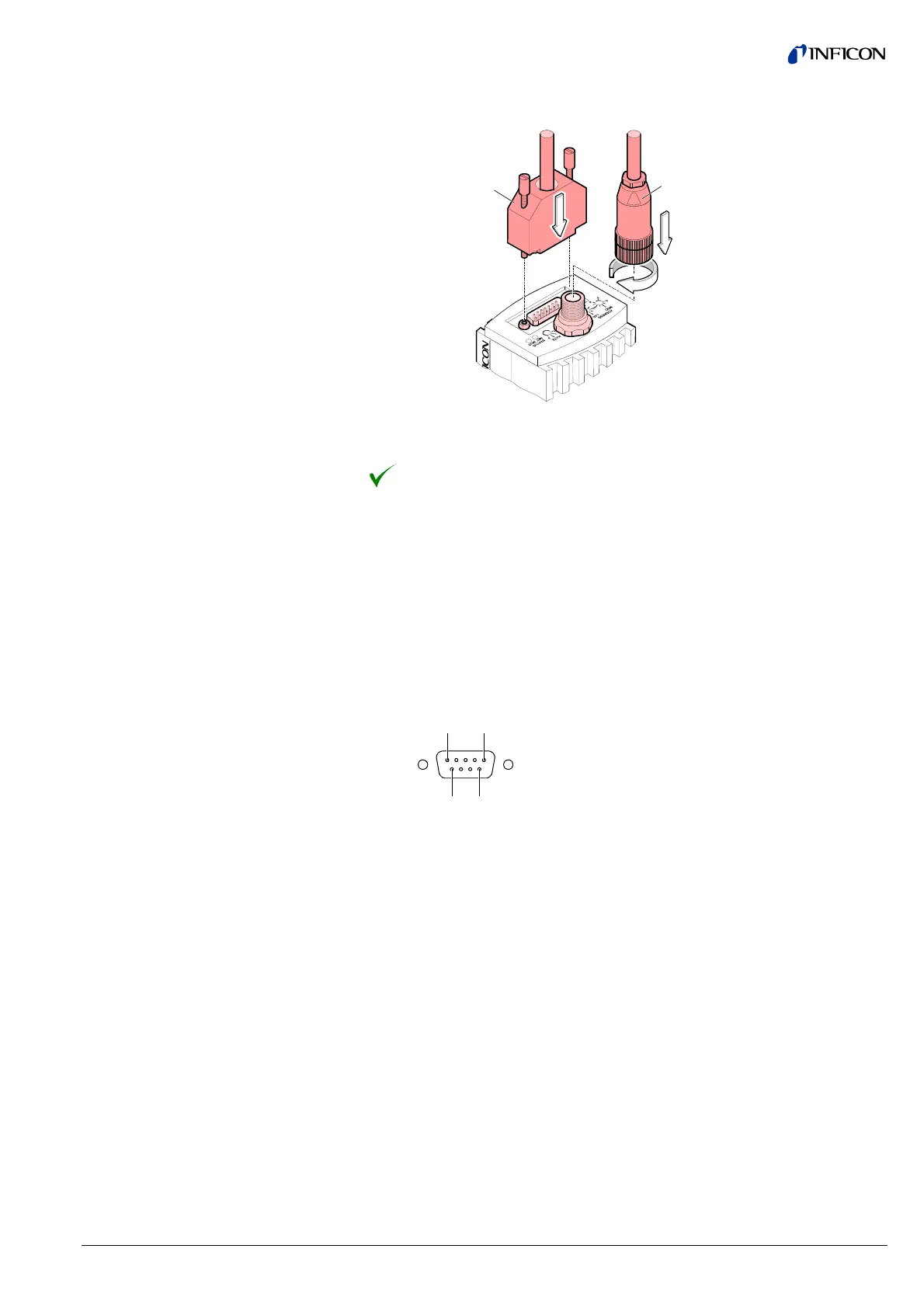
Plug the DeviceNet (and sensor) cable connector into the gauge.
Sensor cable
DeviceNet cable
Lock the DeviceNet (and sensor) cable connector.
The gauge can now be operated via DeviceNet interface (® 2 35).
For operating BPG400-SP via Profibus, an interface cable conforming to the
Profibus standard is required.
If no such cable is available, make one according to the following indications.
Only a cable that is suited to Profibus operation may be used (
® & [5], [7]).
Make the Profibus interface cable according to the following indications:
1 5
6 9
D-Sub, 9 pins
male, soldering side
Pin Function (BPG400-SP)
1 Do not connect
2 Do not connect
3 RxD/TxD-P
4 CNTR-P
1)
5 DGND
2)
6VP
2)
7 Do not connect
8 RxD/TxD-N
9 Do not connect
1)
Only to be connected if an optical link module is used.
2)
Only required as line termination for devices at both ends of bus cable
(
® & [5]).
3.2.2.3 Making a Profibus
Interface Cable
(BPG400-SP)
Cable type
Procedure