tina03e1 (0206) BPG400 v1.om 21
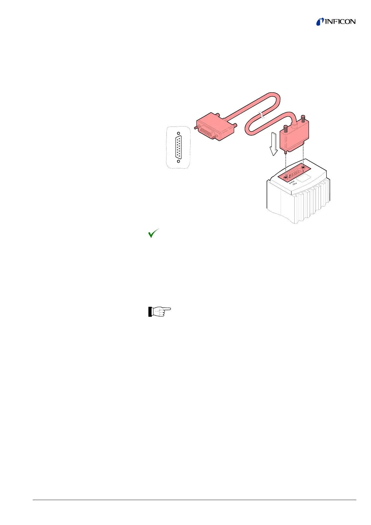
Plug the sensor connector into the gauge and secure it with the locking
screws.
Connect the other end of the sensor cable to the INFICON controller and
secure it.
The gauge can now be operated with the VGC103 or VGC40x controller.
The gauge can also be operated with other controllers.
Especially the fieldbus versions BPG400-SD (DeviceNet) and BPG400-SP
(Profibus) are usually operated as part of a network, controlled by a master or bus
controller. In such cases, the control system has to be operated with the
appropriate software and communication protocol (® & [1] or [10]).
For reasons of compatibility, the expression "sensor cable" is used for all
BPG400 versions in this document, although the pressure reading of the
gauges with fieldbus interface (BPG400-SD and BPG400-SP) is
normally transmitted via DeviceNet or Profibus.
The sensor cable is required for supplying all BPG400 types with power.
In connection with the gauges with fieldbus interface (BPG400-SD and
BPG400-SP), it also permits access to the contacts of the switching
functions (® 2 23, 38).
The application and length of the sensor cable have to be considered when deter-
mining the number and cross sections of the conductors (® 2 9).
Open the cable connector (D-Sub, 15 pins, female).
Prepare the cable and solder/crimp it to the connector as indicated in the
diagram of the gauge used:
Procedure
3.2.2 Use With Other
Controllers
3.2.2.1 Making an Individual
Sensor Cable
Cable type
Procedure