EasyManuals Logo

Inficon BPG400 User Manual

Inficon BPG400
56 pages
To Next Page IconTo Next Page
To Previous Page IconTo Previous Page
Page #22 background imageLoading...
Page #22 background image
22 tina03e1 (0206) BPG400 v1.om
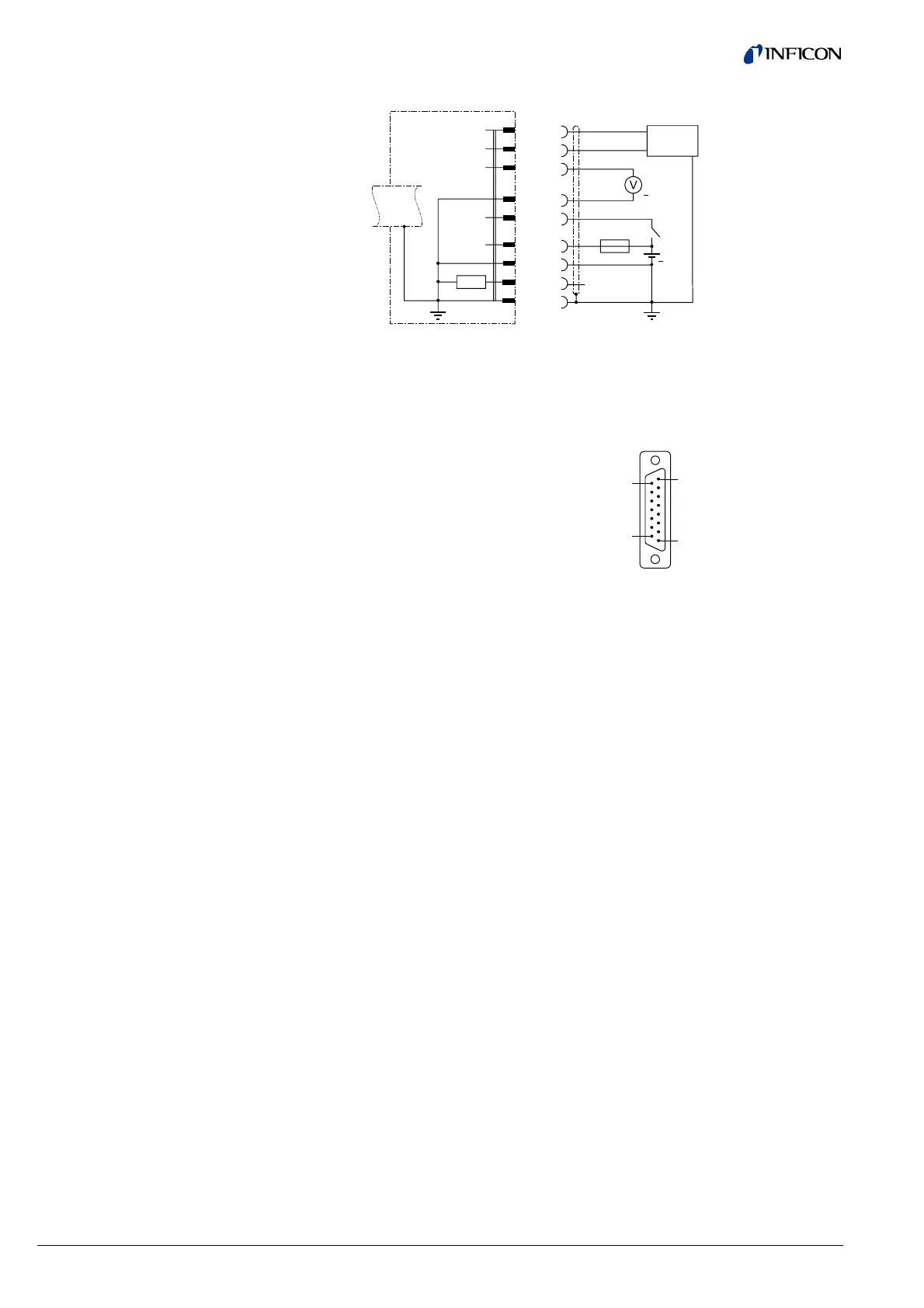
Electrical connection
Pin 2 Signal output (measuring signal)
Pin 5 Supply common, GND
Pin 7 Degas on, active high
Pin 8 Supply
Pin 10 Gauge identification
Pin 12 Signal common, GND
Pin 13 RS232C, TxD
Pin 14 RS232C, RxD
Pin 15 Shielding, housing, GND
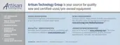
8
9
1
15
+24 VDC
+24 VDC
Pins 1, 3, 4, 6, 9 and 11 are
not connected internally.
0 … +10 V
D-Sub, 15 pins
female,
soldering side
TxD
BPG400
42k
W
RxD
Measuring
signal
Degas
+U
b
13
14
2
12
7
8
5
15
+
1.25AT
Identification
10
RS232C
+
24 V
Sensor cable connection
BPG400

Table of Contents

Other manuals for Inficon BPG400

Questions and Answers:

Question and Answer IconNeed help?

Do you have a question about the Inficon BPG400 and is the answer not in the manual?

Inficon BPG400 Specifications

General IconGeneral
BrandInficon
ModelBPG400
CategoryAccessories
LanguageEnglish