6. Description of Parameters
- 118 -
6
Ƶ
Pulse Reference (DI5)
Frequency reference is input by means of DI5 (high-speed pulse). Signal specification
of pulse reference is 9 to 30 V (voltage range) and 0 to 100 kHz (frequency range). The
corresponding value 100% of pulse reference corresponds to the value of F0-10 (max.
frequency).
Note
Main frequency reference set via pulse reference and pulse output of the FM
terminal (F5-00 = 1) cannot be used simultaneously.
F4-28 to F4-32 set relationship between pulse input (from DI5 only) and corresponding
percentage. It has the same function and usage as AI curve 1 does. Refer to
S
t
e
p
1
:
S
e
t
A
I
c
u
r
v
e
.
Function Code Parameter Name Setting Range Default
F4-28
Pulse min. input 0.00 kHz to F4-30 0.00 kHz
F4-29
Corresponding percentage
of pulse min. input
-100.00% to 100.0% 0.0%
F4-30
Pulse max. input F4-28 to 50.00 kHz 50.00 kHz
F4-31
Corresponding percentage
of pulse max. input
-100.00% to 100.0% 100.0%
F4-32
3XOVH¿OWHUWLPH 0.00s to 10.00s 0.10s
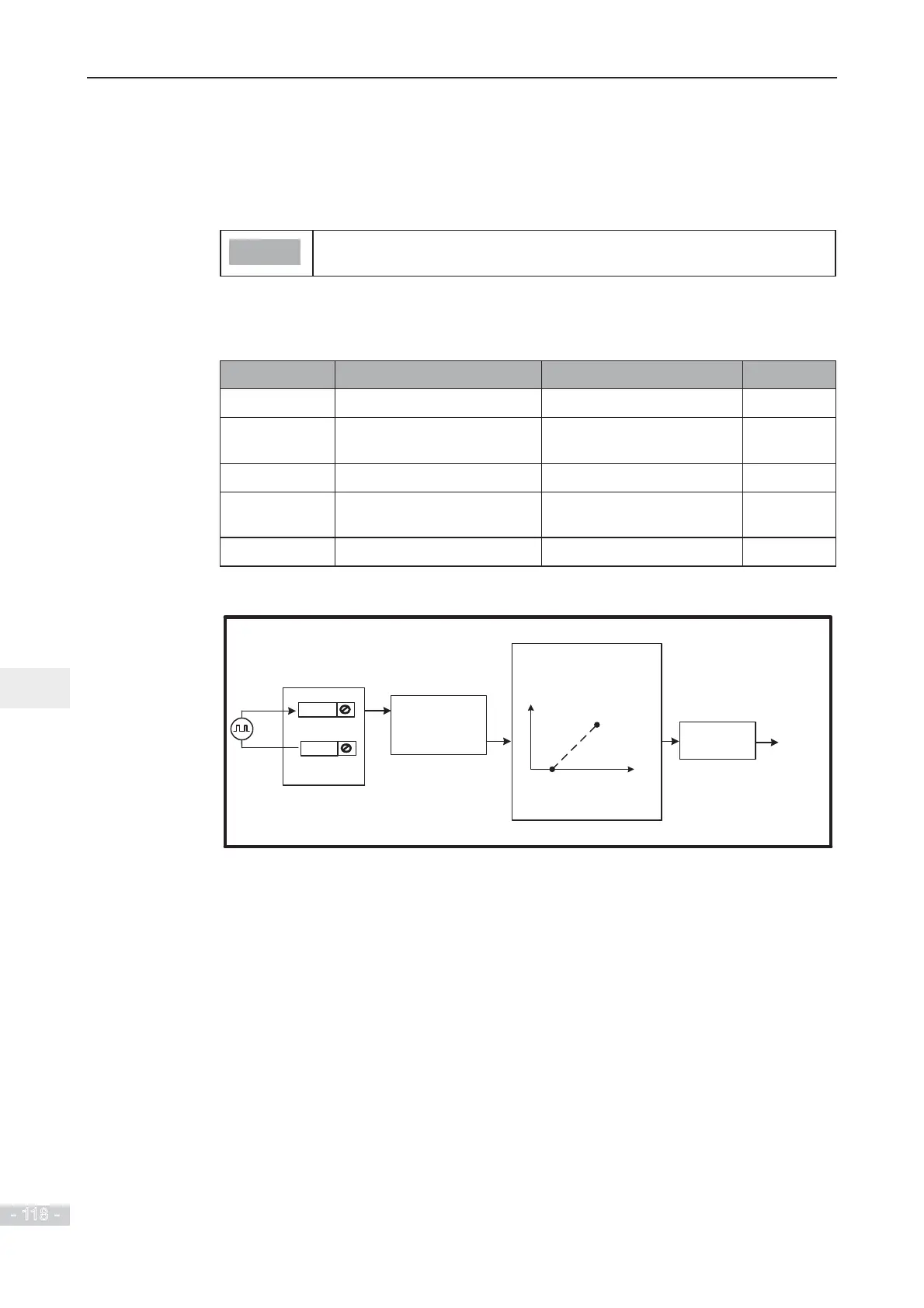
Figure 6-19 Pulse input at DI5 to control frequency reference
Note:
100.0% corresponds to
max. frequency (F0-10).
DI5
Use pulse signals to control
frequency reference
(valid for DI5 only)
COM
Final
frequency
reference
Select main frequency
reference as final
frequency reference.
Set the relationship between
the pulse input (from DI5 only)
and the corresponding
percentage via F4-28 to F4-32.
Select pulse as main
frequency reference
setting channel.
F0-07 (units
position) = 0
F4-33 (hundreds
position) = 2
F0-03 = 5
 Loading...
