6. Description of Parameters
- 117 -
6
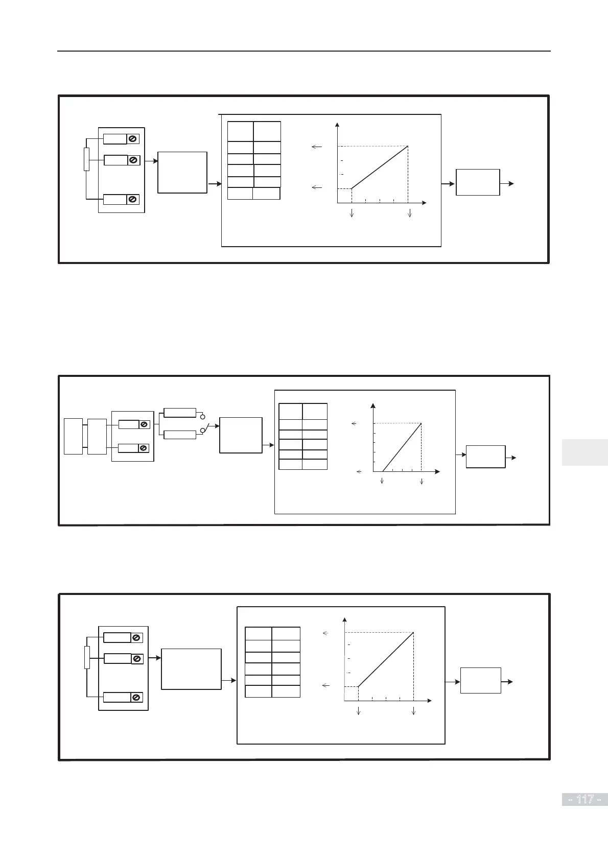
Figure 6-16 Voltage input at AI1 to control frequency reference
Note:
2 to 10 V corresponds to 20.0% to 80.0%.
100.0% corresponds to max. frequency (F0-10 = 50.00 Hz).
AI1
F4-33 (units
position) = 1
Select two-point
curve 1 for AI1
0 to 10 V
Pot.
(2 kȍ)
F4-13
F4-14
2.00
F4-15
F4-16
10.00
F4-17 0.10
AI (V)
80.0
60.0
40.0
20.0
0.00
2.004.006.008.0010.00
F4-14
0.0
F4-13 F4-15
F4-16
percentage (%)
Corresponding
Final
frequency
reference
Select main frequency
reference as final
frequency reference.
Para.
Select AI1 as main
frequency reference
setting channel.
F0-07 (units
position) = 0
+10V
F0-03 = 2
Setting
GND
20.0%
80
.0%
Example 2: On the condition that current input from AI2 is available, if 0 to 20 mA is input,
it corresponds to voltage input of 0 to 10 V. If 4 to 20 mA is input, it corresponds to voltage
input of 2 to 10 V.
To make current input at AI2 to control frequency reference and correspond 4 to 20 mA to
WR+]WKHVHWWLQJVDUHVKRZQLQWKHIROORZLQJ¿JXUH
Figure 6-17 Current input at AI2 to control frequency reference
Note:
4 to 20 mA corresponds to 0.0% to 100.0%.
100.0% corresponds to max. frequency (F0-10 = 50.00 Hz).
AI2
F4-18
F4-19 20.0%
2.00
F4-20
F4-21
10.00
80.0%
F4-22 0.10
Final
frequency
reference
Select main frequency
reference as final
frequency reference.
Para.
AI
(mA)
20.016.0
12.0
8.0
4.0
100.0
0
80.0
60.0
40.0
20.0
0.0
F4-19
F4-21
F4-18
F4-20
Corresponding
percentage (%)
4D/A
module
GND
AO
0 to 10 V
J9
F0-07 (units
position) = 0
F4-33 (units
position
) = 2
Select two-point
curve 2 for AI2
Select AI2 as main
frequency reference
setting channel.
F0-03 = 2
PLC
GND
4 to 20 mA
Setting
Example 3: To make voltage input at AI3 to control frequency reference and correspond 2
WR9WRWR+]WKHVHWWLQJVDUHVKRZQLQWKHIROORZLQJ¿JXUH
Figure 6-18 Voltage input at AI3 to control frequency reference
Note:
2 to 10 V corresponds to 20.0% to 100.0%.
100.0% corresponds to max. frequency (F0-10 = 50.00 Hz).
AI3
-10 to 10 V
+10V
GND
Pot.
(2 kȍ)
F4-23
F4-24 20.0%
2.00
F4-25
F4-26
10.00
F4-27 0.10
AI (V)
80.0
60.0
40.0
20.0
0.00
2.004.00 6.008.0010.00
F4-24
0.0
F4-23 F4-25
F4-26
percentage
(%)
Correspondin
g
Final
frequency
reference
Select main
frequency reference
as final frequency
reference.
Para.
Select AI3 as main
frequency reference
setting channel.
F0-07 (units
position) = 0
100.0
F4-33 (hundreds
position
) = 2
Select two-point
curve 3 for AI3
F0-03 = 4
100.0%
Setting
 Loading...
