6. Description of Parameters
- 116 -
6
Step 2: Select a required curve for AI terminal.
)VHOHFWVFXUYHRI$,$,DQG$,IURPWKH¿YHFXUYHVUHVSHFWLYHO\&XUYHFXUYH
2 and curve 3 are 2-point curves, set in group F4. Curve 4 and curve 5 are 4-point curves,
set in group A6.
The drive provides two AI terminals (AI1, AI2). An extra AI terminal (AI3) is provided by
the I/O extension card.
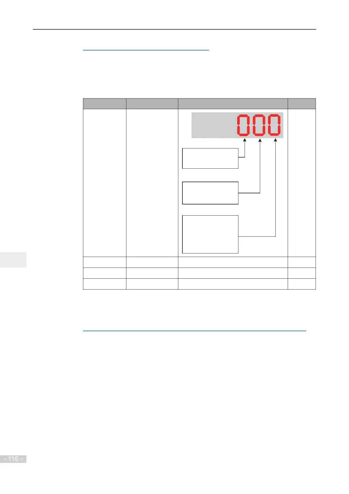
Function Code Parameter Name Setting Range Default
F4-33
AI curve selection
AI2 curve selection
The same as that of
units position
AI1 curve selection
1: Curve 1
2: Curve 2
3: Curve 3
4: Curve 4
5: Curve 5
AI3 curve selection
The same as that of
units position
321
F4-17
$,¿OWHUWLPH 0.00s to 10.00s 0.10s
F4-22
$,¿OWHUWLPH 0.00s to 10.00s 0.10s
F4-27
$,¿OWHUWLPH 0.00s to 10.00s 0.10s
))DQG)VHW$,VRIWZDUH¿OWHUWLPH,IDQDORJLQSXWLVOLDEOHWRLQWHUIHUHQFH
increase this parameter to stabilize detected analog input. But too large a setting slows
response of analog detection. Set it correctly based on actual conditions.
Step 3: Select a required AI terminal as main frequency reference setting channel.
The AC drive provides two AI terminals (AI1, AI2). An extra AI terminal (AI3) is provided by
the I/O extension card.
Here takes each AI terminal as examples to show how to use AI terminal to control main
frequency reference.
Example 1: To make voltage input at AI1 to control frequency reference and correspond 2
WR9WRWR+]WKHVHWWLQJVDUHVKRZQLQWKHIROORZLQJ¿JXUH
 Loading...
