3. Electrical Installation
- 64 -
3
Ƶ
Braking Resistor
CAUTION
Ɣ Fire risk! Fit overtemperature sensors or thermal overload relay to
the braking resistor, and use double insulated cables for the dynamic
brake circuit to the brake resistors.
Ɣ Braking resistor terminals (+) and PB are only for the drive units up to
N:WKDWDUH¿WWHGZLWKDQLQWHUQDOEUDNLQJXQLW
Ɣ
To avoid risk of equipment damage, use a cable not exceeding 5 m to
connect an external braking resistor.
Ɣ To avoid risk of ignition due to overheating of the braking resistor, do
not place anything combustible around the braking resistor.
Ɣ
Set F6-15 (Braking use ratio) and F9-08 (Braking unit action initial
voltage) correctly according to load after connecting braking resistor to
WKHGULYHRIXSWRN:WKDWLV¿WWHGZLWKDQLQWHUQDOEUDNLQJXQLW
Ƶ
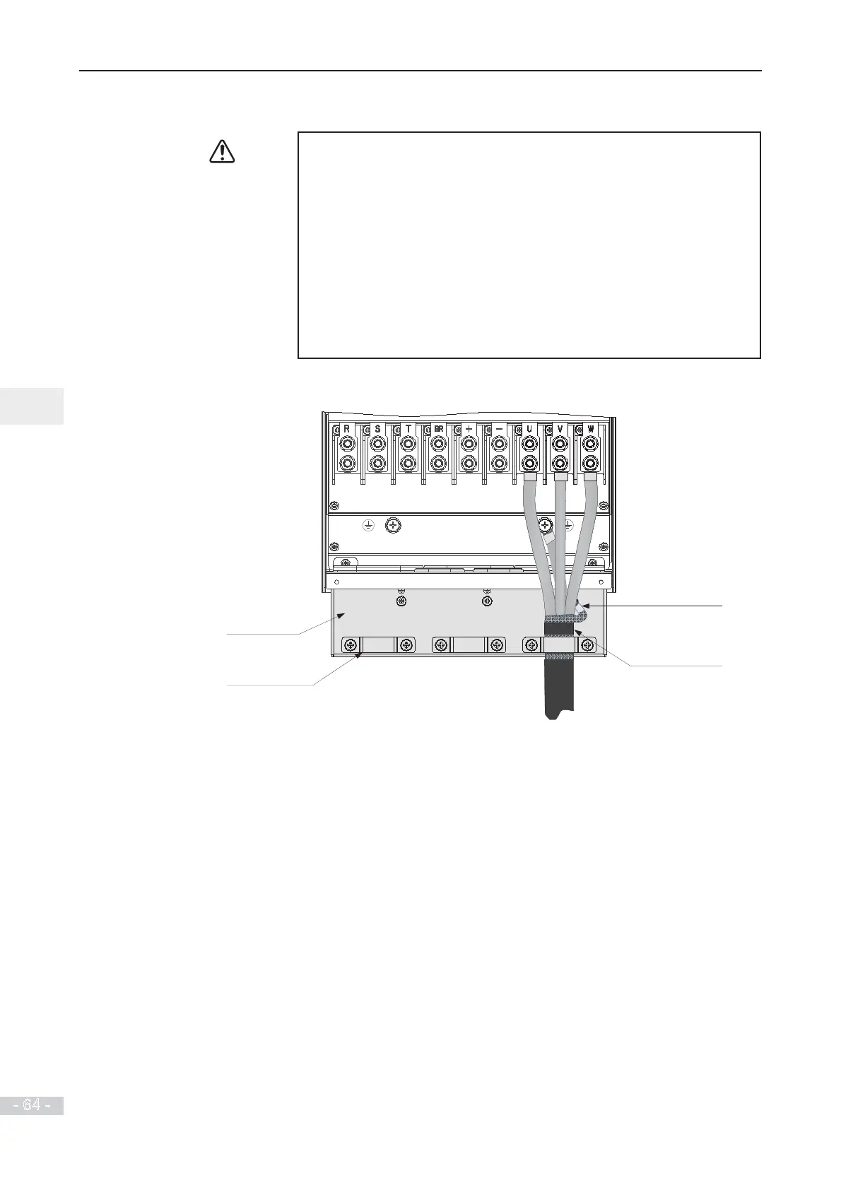
AC Drive Outputs U, V, W to Motor
Grounding clamp
for screen/shield
Main circuit cables
Cable support
bracket (option)
Use heatshrink tube or
insulation tape to terminate
the screen/shield.
Screen/shield
 Loading...
