3. Electrical Installation
- 70 -
3
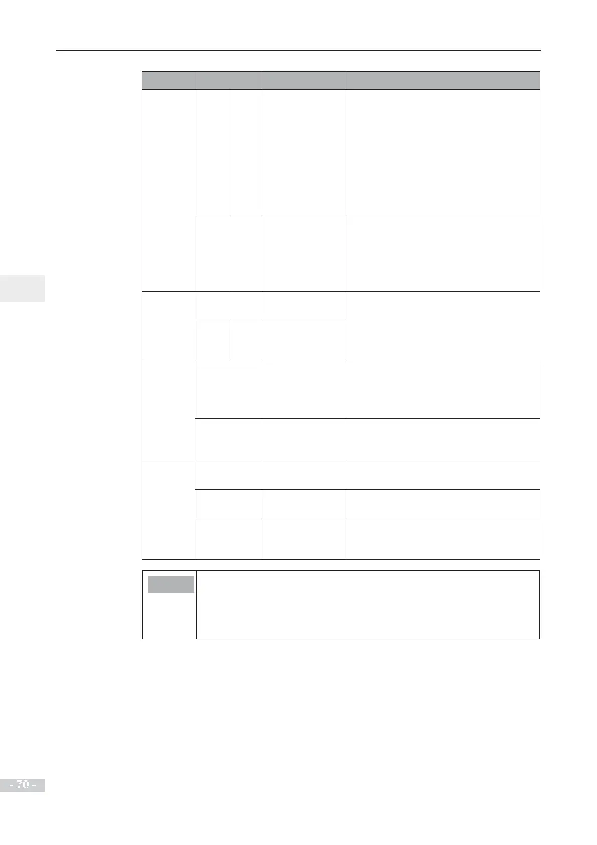
Type Terminal
Name
Description
Digital
outputs
DO1 CME Digital output 1 Optically-coupled isolation, dual-polarity
open-collector output
Output voltage range: 0 to 24 V
Output current range: 0 to 50 mA.
Note that CME and COM are internally
insulated, but are shorted externally by a
jumper. In this case, DO1 is driven by +24
V by default. Remove the jumper link if
you need to apply external power to DO1.
FM COM High-speed pulse
output
Controlled by F5-00 (FM terminal output
selection).
Max. output frequency: 100 kHz.
When used as an open-collector output,
WKHVSHFL¿FDWLRQLVWKHVDPHDVIRU'2
Relay
outputs
T/A T/B Normally-closed
(NC) terminal
Contact driving capacity:
250 VAC, 3 A, Cos f = 0.4
30 VDC, 1 A
Applies to overvoltage Category II circuit
T/A T/C Normally-open
(NO) terminal
Auxiliary
interfaces
J13 Extension card
interface
Interface for the 28-core terminal and
optional cards
(I/O extension card, PLC card and various
bus cards)
J11 External
operating panel
interface
Connected to an external operating panel.
Jumpers
<2>
J7 AO1 output
selection
Either a voltage or a current output,
voltage output by default
J9 AI2 input
selection
Either a voltage or a current input, voltage
input by default.
J10 AI2 input
impedance
selection
(LWKHUȍRUȍLQSXWȍLQSXW
by default
Note
Ɣ
<1>
6HOHFWȍRUȍLQSXWLPSHGDQFHDFFRUGLQJWRZLWKORDGFDSDFLW\
RIVLJQDOVRXUFH)RUH[DPSOHLIȍLVVHOHFWHGPD[LPXPRXWSXW
voltage of signal source must not be smaller than 10 V so that AI2 can
measure 20 mA current.
Ɣ
<2>
: For positions of jumpers J7, J9 and J10, refer to
F
i
g
u
r
e
3
-
1
7
.
 Loading...
