3. Electrical Installation
- 71 -
3
3.3.2 Wiring Diagrams
Ƶ
Selection of Control Circuit Wirings
All control wirings must be shielded.
For different analog signals, use independent shielded cables and do not use the same
shield.
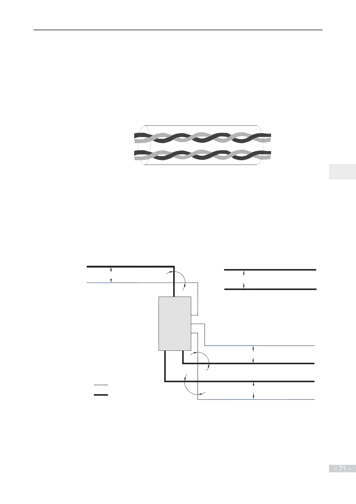
For digital signals, shielded twisted pair (STP) cable is recommended.
STP cable
.
Ƶ
Cabling Requirements
Ɣ
Motor cables must be segregated from control wiring to minimize electrical
interference from the PWM effects of the motor cable.
Ɣ
Do not run motor cables, power input cables and control wirings in the same duct to
avoid electromagnetic interference caused by coupling of these cables.
Ɣ
If control wiring must run across power cable, ensure they are arranged at an angle of
90°.
The recommended cabling diagram is as follows:
MD290
Min. 200 mm
Min. 300 mm
Power supply cable
Motor cable
Min. 500 mm
Min. 500 mm
Braking resistor
cable
Motor cable
Power supply cable
90°
90°
90°
Control wiring
Control wiring
Power supply cable
Control wiring
Control wiring
 Loading...
