3 Easy Setup
- 19 -
Para� No� Para� Name Setting Range Unit Default Commission
F4-03 DI4 function selection 22: PID pause
23: PLC status reset
24: Wobble pause
25: Counter input
26: Counter reset
27: Length count input
28: Length reset
29: Torque control prohibited
30: Pulse input (enabled only for DI5)
31: Reserved
32: Immediate DC injection braking
33: External fault normally closed (NC) input
34: Frequency modication forbidden
35: PID action direction reverse
36: External STOP terminal 1
37: Command source switchover terminal 2
38: PID integral disabled
39: Switchover between main frequency
source X and preset frequency
40: Switchover between auxiliary frequency
source Y and preset frequency
41: Motor selection terminal 1
42: Reserved
43: PID parameter switchover
44: User-dened fault 1
45: User-dened fault 2
46: Speed control/Torque control switchover
47: Emergency stop
48: External STOP terminal 2
49: Deceleration DC injection braking
50: Clear the current running time
51: Two-wire/Tree-wire switchover
52: Reverse frequency prohibited
53–59: Reserved
N�A� 12
Multi-reference
terminal 1
F4-04 DI5 function selection N�A� 13
Multi-reference
terminal 2
F4-10 DI lter time 0�000 to 1�000 s 0�010
F4-35 DI1 delay 0�0 to 3600�0 s 0�0
F4-36 DI2 delay 0�0 to 3600�0 s 0�0
F4-37 DI3 delay 0�0 to 3600�0 s 0�0
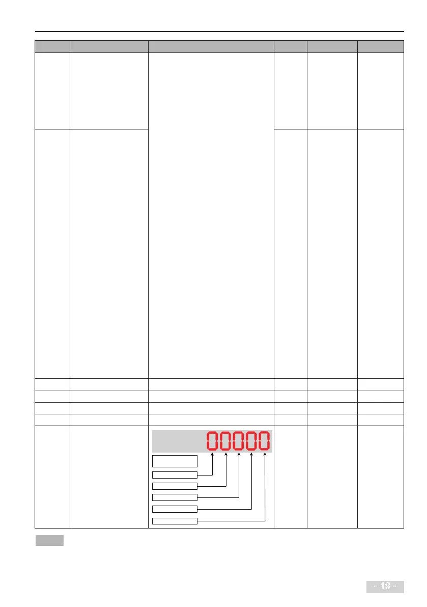
F4-38 DI active mode selection 1
0: High level active
1: Low level active
DI5 active mode
DI4 active mode
DI3 active mode
DI2 active mode
DI1 active mode
N�A� 00000
High level active means that, if a high level voltage is applied to DI terminal, the DI signal will be seen as active�
Low level active means that, if a low level voltage is applied to DI terminal, the DI signal will be seen as active�
 Loading...
