6
1. Inside connection: 4-20mA, load input port connect with “I” of J602, Ground
port connect with “ GND” of J602
2. Outside connection: 4-20mA, load input port connect with “1” pin of DB9,
Ground port connect with “6” pin of DB9
Testing :
Connect the 250Ω to the 4-20mA, adjust the multimeter to the current stalls, the
red pan connect the loading port, and the black pan connect” GND” to test the
output current.
Calibration:
1. Press” Print” and “ Total” go to C32, show[out-4], the output current should be
4mA.
2. If Press [↑]show[out-5],Pres[↓]show[out-20],the output current should be
20mA.
3. Adjust the current, for example, adjust to [out-20], Press [←](“Zero”
key)or[→](Net/gross key)to adjust the current
Function instruction:
4~20mA correspond to Zero ~Max. capacity. After press” TARE”, the weight will
start from 4mA. SET C31=0, 0~20mA output mode.; C31=1 4~20mA output mode.
If you need 0~5V output, Set C31=0, Then connect 250Ω at the two ends of
current output., will get 5voltage at resistance two ends
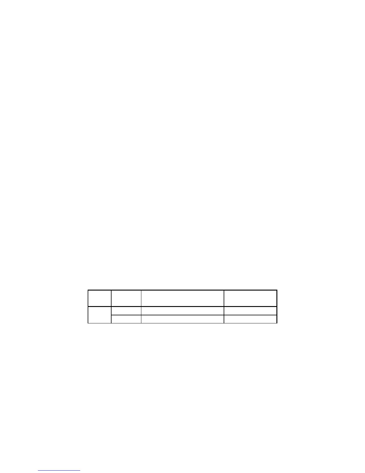
Relay output signal function
The indicator can output 4 signal , connect with the outside equipment
the indicator can perform automatic control function and upper limit
and lower limit alarm function. Perform the 4 kinds function through
setting C33, 4 signals
As below
Output
port
Port definition Function
C33=0
Out1 Close output function No output signal
Out2 Close output function No output signal