23
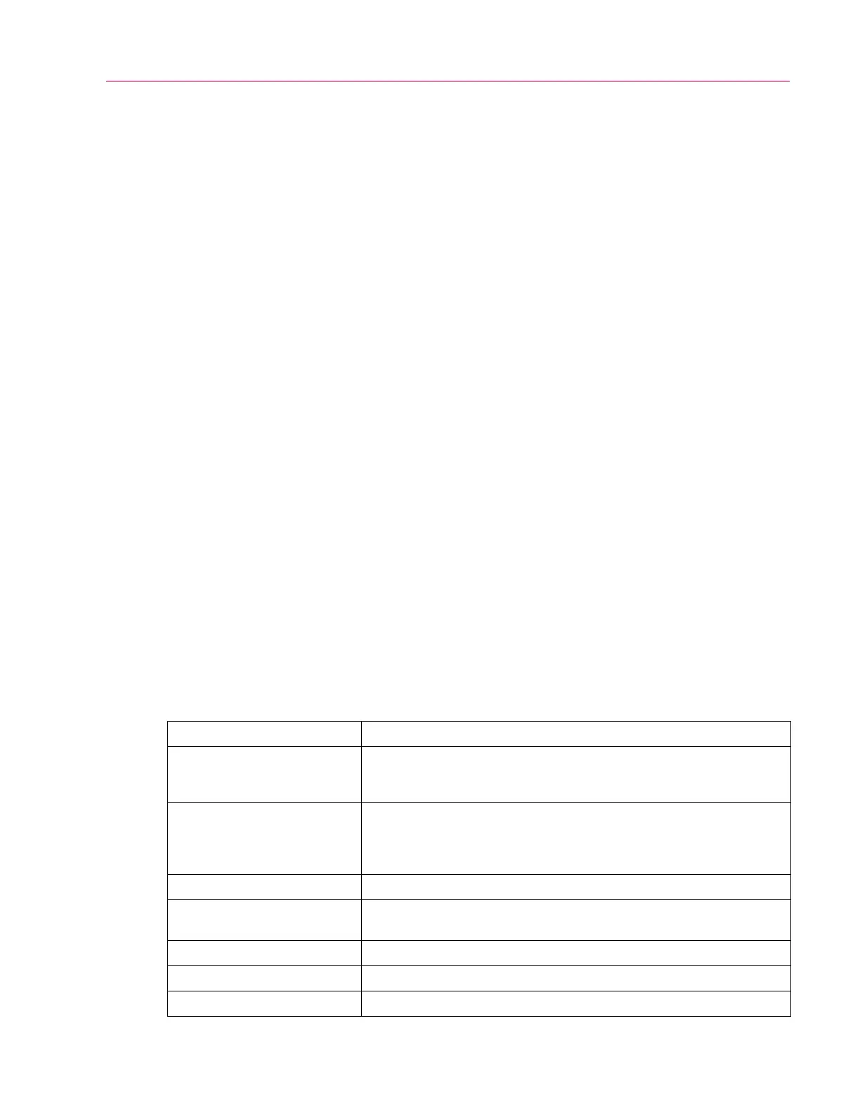
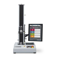
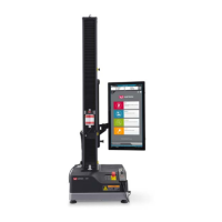
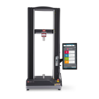
59 Series control unit
Product Support: www.instron.com
59 Series control unit
1. J1 = Manually adjustable crosshead with manual crosshead locks
J3 = Hydraulically adjustable crosshead with hydraulic crosshead locks
H1 = Anti-rotation only, no guidance
H2 = Heavy-duty guidance
E1 = Standard tension opening
E2 = Extended tension opening by:
- 356 mm (14 in) for 300LX frames
- 406.4 mm (16 in) for 600LX frames
E3 = Extended tension opening by:
- 889 mm (35 in) for 300LX frames
- 1016 mm (40 in) for 600LX framess
2. Long term static tests should be limited to 30 minutes or less when the test is performed at or near maximum capacity. Time
varies inversely with test load. 50% maximum capacity tests should be limited to 60 minutes or less. An oil temperature
switch limits test duration based on safe reservoir temperature. Assumes ambient temperature of 25 deg C (77 deg F).
3. The design capacity is the peak load at which the frame should be used for no more than 80% of the time. In other words, at
least 80% of specimen testing should be conducted at peak loads that are at or below the design capacity. The frame should
only be used at loads between the design capacity and the maximum capacity less than 20% of the time.
4. For J1-style crossheads, the minimum and maximum test opening is provided for each notch position of the crosshead. First
notch position is with the crosshead in the lowest notch on the columns. Number of notch positions provided depends on
frame height option purchased; not all frames have all notch positions listed.
Minimum opening is with the hydraulic cylinder fully extended. Maximum opening is with the hydraulic cylinder fully retracted.
Values do not include specimen fixtures.
5. The General Assembly drawing is located in the separately supplied “Reference Manual-Equipment”. General Assembly
drawings are model specific; please be sure to refer to the appropriate drawing for your model and its configuration.
6. Under no load conditions. Accuracy is affected under load. The encoder cannot compensate for frame deflection (axial
stiffness) or the load cell and load string deflections. Over short travels and higher loads, the error could be over 100%.
Conversely, over longer travels and lower loads, the error may be insignificant. The axial frame stiffness and load cell stiffness
values published may be used to assess this affect. The load string also needs to be considered. In general, the extension
(position) readout should not be used as the primary strain measuring device where an extensometer on the specimen is
clearly warranted. Frame compliance can be accounted for to some extent by Instron software.
7. At speeds below approximately 0.1 mm/min (0.004 in/min) the hydraulic cylinder moves in increments approximately equal to
these values and can be seen as load steps depending on the specimen stiffness and load range.
8. Center alignment is a theoretical value based on the tolerance accumulation of machined components. Use of grips and
fixtures will affect this estimate. In applications requiring precision alignment, an alignment device is recommended.
Table 6. 59 Series control unit technical specifications.
Data Sampling 40 kHz
Data Capture Selectable up to 1000 Hz
1
Intelligent data capture
Synchronous on all channels
Digital Signal Processor 32-bit floating point
Self-test diagnostics
Real-time closed-loop control
Real-time data acquisition
Data Transfer to Computer 1000 Hz
Transducer Inputs Standard Instron rationalized transducers
Any 0-10 V analog DC input
Transducer Resolution 1 part in 500,000 of +/- full scale (19 bits)
Load Measurement Accuracy +/- 0.5% of reading down to 1/500 of load cell capacity
Linearity +/- 0.25% of reading over a range of 0.2% to 100% of capacity


 To Next Page