Chapter 3: Operation
36 M47-17041-EN
• To raise the crosshead, retract the hydraulic cylinder so that it has enough stroke to extend and
lift the crosshead.
3. Place the lumber, as necessary, between the hydraulic cylinder and load cell. If fixtures are installed
in the test space, the lumber can typically be placed between the fixtures without damage to them.
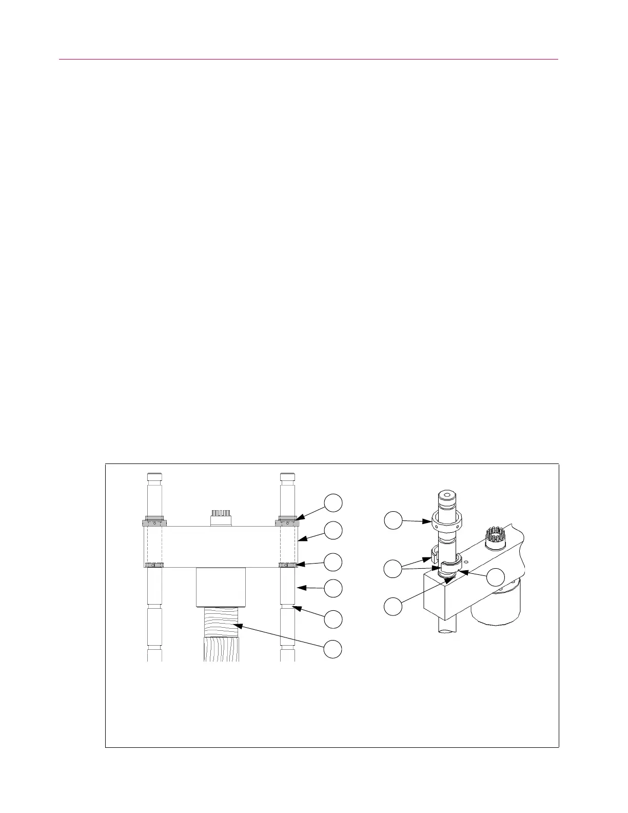
4. Loosen and remove the collar (1a, Figure 8) from one of the threaded retaining rings (1) in the notch
above the crosshead (use spanner wrench). This will expose the threaded sleeves (1b) of the
retaining ring. Remove the threaded sleeves from the column and place them with their collar.
Repeat to remove the other threaded retaining ring. Be sure to keep the parts of each threaded
retaining ring together as they are a matched set and should not be interchanged. If they are
interchanged, the collar may not thread back on the sleeves properly and could become jammed.
5. Extend the hydraulic cylinder to raise the crosshead so that the split retaining rings (3) are exposed.
6. Loosen the two socket head cap screws (SHCS) of one split retaining ring and remove the split
retaining ring from the notch (use 5/16 in hex key). Repeat to remove the other split retaining ring.
7. Operate the hydraulic cylinder until the lower surface of the crosshead is slightly above the desired
notch.
8. Place a split retaining ring into each new lower notch and tighten the socket head cap screws of each
split retaining ring until seated plus one-quarter turn.
9. Lower the crosshead to rest on the split retaining rings. The split retaining rings will fit into the
recesses on the bottom of the crosshead.
10. Place the two sleeves of one threaded retaining ring in the new upper notch of one column. A notch
in the bottom edge of each sleeve will fit over a pin in the crosshead to ensure proper alignment (see
Figure 8). Once the sleeves are in place, thread the collar onto the sleeves. Tighten the collar until
seated plus one-quarter turn (use spanner wrench). Repeat to install the remaining threaded
retaining ring on the other column.
11. Retract the hydraulic cylinder and remove the lumber.
12. Normal operation can now resume.
Figure 8. Adjustment of J1-style crosshead.
1. Threaded retaining ring
a. Collar
b. Sleeve
c. Notch in sleeve
2. Crosshead
3. Split retaining ring
(in recess of crosshead)
4. Column
5. Notch
6. Blocks of lumber
7. Ali gnme n t pi n
1
2
3
4
5
6
1a
1b
7
1c


 To Next Page