Instruction Manual CVM201 Super Bee
InstruTech, Inc. Page 10
3.2 Electrical Installation
3.2.1 Grounding
Be sure the vacuum gauge and the rest of your vacuum system are properly grounded to protect personnel
from shock and injury. Be aware that some vacuum fittings, especially those with O-rings when not used with
metal clamps, may not produce a good electrical connection between the gauge and the chamber it is
connected to.
3.2.2 Electrical Connections
A good recommended practice is to remove power from any cable prior to connecting or disconnecting it.
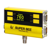
The InstruTech CVM201 will directly replace Granville-Phillips®
Mini-Convectron® modules that have a 9-pin
D-sub connector (DE-9P) or 15-pin D-sub connector (DE-15P), and you can use your existing cables and
electronics. For new installations, fabricate a cable to connect to the signals/functions you want to use. Signals
and pin assignments are described below:
Connector and Pinout
Analog Output 1 (Log-Linear 1-8V, or Non-linear Granville-Phillips®
Mini-Convectron ®compatible)
Relay Disable (Disables both Relays when connected to pin 4 - Ground)
Analog Output 2 (Programmable Linear 0-10 V)
RS485 DATA B (+) Input/output
RS485 DATA A (-) Input/output
Analog Output 1 (Log-Linear 1-8 V, or Non-linear Granville-Phillips®
Mini-Convectron ®compatible)
Relay Disable (Disables both Relays when connected to pin 4 - Ground)