Technical Reference
47
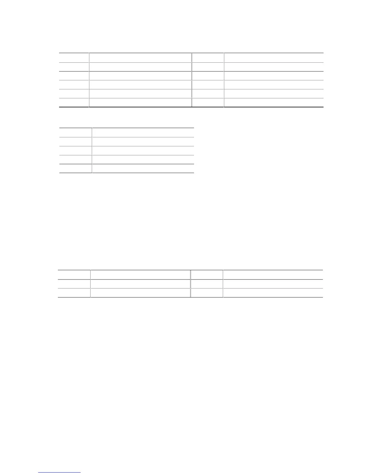
Table 17. Front Panel Audio Connector
Pin Signal Name Pin Signal Name
1 MIC_IN 2 Ground
3 MIC_BIAS 4 +5 V
5 RIGHT_OUT 6 RIGHT_IN
7 No connect 8 Key
9 LEFT_OUT 10 LEFT_IN
Table 18. ATAPI CD-ROM Connector
Pin Signal Name
1 Left audio input from CD-ROM
2 CD audio differential ground
3 CD audio differential ground
4 Right audio input from CD-ROM
#
INTEGRATOR’S NOTES
• Use only ATX12V-, SFX12V-, or TFX12V-compliant power supplies with this board. ATX12V,
SFX12V, and TFX12V power supplies have an additional power lead that provides required
supplemental power for the processor. Always connect the 20-pin and 4-pin leads of ATX12V,
SFX12V, and TFX12V power supplies to the corresponding connectors on the Desktop Board,
otherwise the Desktop Board will not boot.
• Do not use a standard ATX power supply. The Desktop Board will not boot with a standard
ATX power supply.
Table 19. ATX12V Power Connector
Pin Signal Name Pin Signal Name
1 Ground 2 Ground
3 +12 V 4 +12 V