Contents
v
Boot Menu...........................................................................................................................58
Boot Device Priority Submenu....................................................................................59
Hard Disk Drives Submenu ........................................................................................59
Removable Devices Submenu....................................................................................60
ATAPI CD-ROM Drives ..............................................................................................60
Exit Menu ............................................................................................................................61
5 Technical Reference
Board Connectors ...............................................................................................................63
Back Panel Connectors ..............................................................................................64
Audio Connectors .......................................................................................................65
Add-In Card and Peripheral Interface Connectors ......................................................66
Desktop Board Resources...................................................................................................67
Memory Map ..............................................................................................................67
DMA Channels ...........................................................................................................67
Interrupts ....................................................................................................................68
A Error Messages and Indicators
BIOS Beep Codes...............................................................................................................69
BIOS Error Messages .........................................................................................................70
B Regulatory Compliance
Safety Regulations ..............................................................................................................73
EMC Regulations ................................................................................................................73
Product Certification Markings.............................................................................................74
Installation Precautions .......................................................................................................75
Installation Instructions........................................................................................................75
Ensure Electromagnetic Compatibility (EMC) Compliance .........................................75
Chassis and Component Certifications.......................................................................76
Prevent Power Supply Overload.................................................................................76
Place Battery Marking ................................................................................................76
Use Only for Intended Applications.............................................................................76
Figures
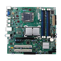
1. Desktop Board D845GERG2 Components .................................................................... 9
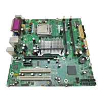
2. Desktop Board D845GEBV2 Components....................................................................10
3. Location of Standby Power Indicator.............................................................................18
4. Installing the I/O Shield.................................................................................................22
5. Location of Desktop Board Mounting Holes ..................................................................23
6. Installing a Processor....................................................................................................24
7. Connecting the Processor Fan Heat Sink Cable to the Processor Fan Connector........25
8. Installing a Memory Module ..........................................................................................26
9. Removing the AGP or ADD Card..................................................................................28
10. Connecting the IDE Cable.............................................................................................29
11. Front Panel Headers.....................................................................................................30
12. Location of Fans and Power Connectors ......................................................................33
13. Location of the BIOS Configuration Jumper Block ........................................................34
14. Removing the Battery ...................................................................................................38
 Loading...