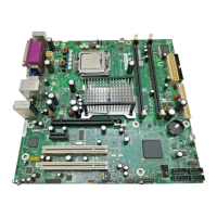
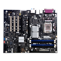
Product Description
23
1.5.2.3 Serial ATA RAID
The ICH7-R supports the following RAID (Redundant Array of Independent Drives) levels:
• RAID 0 - data striping. Multiple physical drives can be teamed together to create one logical
drive. As data is written or retrieved from the logical drive, both drives operate in parallel, thus
increasing the throughput. The ICH7-R allows for more than two drives to be used in a
RAID 0 configuration.
• RAID 1 - data mirroring. Multiple physical drives maintain duplicate sets of all data on
separate disk drives. Level 1 provides the highest data reliability because two complete copies
of all information are maintained. The ICH7-R allows for two or four drives to be used in a
RAID 1 configuration.
• RAID 0+1 (or RAID 10) - data striping and mirroring. RAID 0+1 combines multiple mirrored
drives (RAID 1) with data striping (RAID 0) into a single array. This provides the highest
performance with data protection. Data is striped across all mirrored sets. RAID 0+1 utilizes
several drives to stripe data (increased performance) and then makes a copy of the striped
drives to provide redundancy. The mirrored disks eliminate the overhead and delay of parity.
• RAID 5 - distributed parity. RAID Level 5 stripes data at a block level across several drives
and distributes parity among the drives; no single disk is devoted to parity. Because parity data
is distributed on each drive, read performance tends to be lower than other RAID types.
RAID 5 requires the use of three or four drives.
1.5.2.4 SCSI Hard Drive Activity LED Connector (Optional)
The SCSI hard drive activity LED connector is a 1 x 2-pin connector that allows an add-in
hard drive controller to use the same LED as the onboard IDE controller. For proper operation, this
connector should be wired to the LED output of the add-in hard drive controller. The LED
indicates when data is being read from, or written to, either the add-in hard drive controller or the
onboard IDE controller (Parallel ATA or Serial ATA).
For information about Refer to
The location of the SCSI hard drive activity LED connector Figure 19, page 56
The signal names of the SCSI hard drive activity LED connector Table 23, page 59
1.5.3 Real-Time Clock, CMOS SRAM, and Battery
A coin-cell battery (CR2032) powers the real-time clock and CMOS memory. When the computer
is not plugged into a wall socket, the battery has an estimated life of three years. When the
computer is plugged in, the standby current from the power supply extends the life of the battery.
The clock is accurate to ± 13 minutes/year at 25 ºC with 3.3 VSB applied.
NOTE
If the battery and AC power fail, custom defaults, if previously saved, will be loaded into CMOS
RAM at power-on.
 Loading...