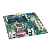
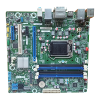
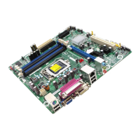
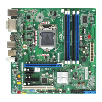
Intel Desktop Board DQ77KB Technical Product Specification
x
22. Intel MEBX Reset Header ................................................................... 71
23. Board Dimensions ............................................................................. 73
24. Localized High Temperature Zones ..................................................... 77
25. Intel Desktop Board DQ77KB China RoHS Material
Self Declaration Table ...................................................................... 104
Tables
1. Specification Changes or Clarifications ................................................... iii
2. Feature Summary ............................................................................. 13
3. Components Shown in Figure 1 .......................................................... 16
4. Components Shown in Figure 2 .......................................................... 17
5. Supported Memory Configurations ...................................................... 21
6. HDMI Port Status Conditions .............................................................. 24
7. DisplayPort Status Conditions ............................................................. 25
8. Audio Formats Supported by the DisplayPort Interface .......................... 25
9. Audio Jack Support ........................................................................... 31
10. LAN Connector LED States ................................................................. 36
11. Intel ME “M” State LED Behavior ........................................................ 42
12. Effects of Pressing the Power Switch ................................................... 43
13. Power States and Targeted System Power ........................................... 44
14. Wake-up Devices and Events ............................................................. 45
15. System Memory Map......................................................................... 51
16. Connectors and Headers Shown in Figure 14 ........................................ 54
17. Components Shown in Figure 15 ........................................................ 55
18. Serial Port Connector ........................................................................ 56
19. Front Panel Audio Header for Intel HD Audio ........................................ 56
20. Front Panel Audio Header for AC ’97 Audio ........................................... 56
21. Front Panel USB 2.0 Connectors ......................................................... 56
22. PCI Express Full-/Half-Mini Card Connector .......................................... 57
23. SATA Connectors .............................................................................. 58
24. Chassis Intrusion Header ................................................................... 58
25. Processor and System (4-Pin) Fan Headers .......................................... 59
26. LPC Debug Connector ........................................................................ 59
27. Internal Stereo Speakers Connector .................................................... 59
28. DMIC Header ................................................................................... 59
29. Dual-Port Front Panel USB 2.0 Headers ............................................... 60
30. Single-Port USB 2.0 Header ............................................................... 60
31. Panel Voltage Selection Header .......................................................... 60
32. Backlight Inverter Voltage Selection Header ......................................... 60
3
3. 40-Pin LVDS Connector ..................................................................... 61
34. 40-Pin eDP Connector ....................................................................... 62
35. 8-Pin FPD Brightness Connector ......................................................... 62
36. PANEL_OFF Header ........................................................................... 62
37. Custom Solutions Header .................................................................. 63
38. Internal Power Supply Connector Pinout .............................................. 63
39. Front Panel Header ........................................................................... 64
 Loading...
