Technical Reference
59
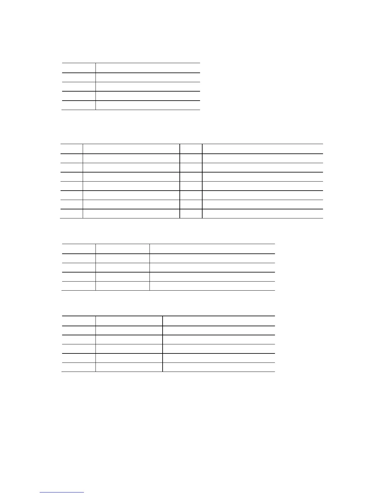
Table 25. Processor and System
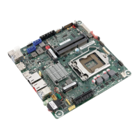
(4-Pin) Fan Headers
Pin Signal Name
1 Ground
(Note)
2 +12 V
3 FAN_TACH
4 FAN_CONTROL
Note: These fan headers use Pulse Width Modulation control for fan speed.
Table 26. LPC Debug Connector
Pin Signal Name Pin Signal Name
1 CK_33M_DEBUG 2 GND
3 PLTRST# 4 LFRAME#
5 LAD0 6 LAD1
7 LAD2 8 LAD3
9 GND 10 GND
11 +3.3 V 12 +3.3 V
13 Key (no pin) 14 +3.3 V
Table 27. Internal Stereo Speakers Connector
Pin Signal Name Description
1 Front_L− Analog front left (differential negative)
2 Front_L+ Analog front left (differential positive)
3 Front_R+ Analog front right (differential positive)
4 Front_R− Analog front right (differential negative)
Table 28. DMIC Header
Pin Signal Name Description
1 +3.3 V 3.3 V power (for DMIC module)
2 DMIC_DATA DMIC data signal
3 GND Ground
4 DMIC_CLK Multiplexed DMIC clock signal
5 Key (no pin) Key (no pin)