Intel Desktop Board DQ77MK Technical Product Specification
52
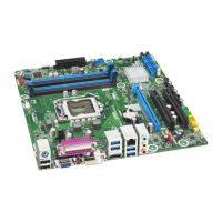
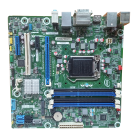
Table 14 lists the component-side connectors and headers identified in Figure 11.
Table 14. Component-side Connectors and Headers Shown in Figure 11
Item/callout f
rom Figure 11
Description
A PCI Express x4 add-in card connector
B Conventional PCI add-in card connector
C IEEE 1394a front panel connector
D PCI Express x1 add-in card connector
E PCI Express x16 add-in card connector
F 12 V processor core voltage connector (2 x 2 pin)
G Rear chassis fan header
H Processor fan header
I Front chassis fan header
J LPC Debug header
K Chassis intrusion header
L Main power connector (2 x 12)
M Intel MEBX reset header
N PCI Express Full-/Half-Mini Card slot
O SATA 6.0 Gb/s connector (multiplexed with an mSATA port, routed to the PCI
Express Full-/Half-Mini Card slot) (gray)
P SATA 3.0 Gb/s connectors through the PCH (black)
Q Alternate front panel power/sleep LED header
R Front panel connector
S SATA 6.0 Gb/s connectors through the PCH (blue)
T Front panel USB 3.0 connector (blue)
U Front panel USB 2.0 connector
V Front panel USB 2.0 connector
W Serial port connector
X S/PDIF out header
Y Front panel audio connector
Z Internal mono speaker header