Technical Reference
57
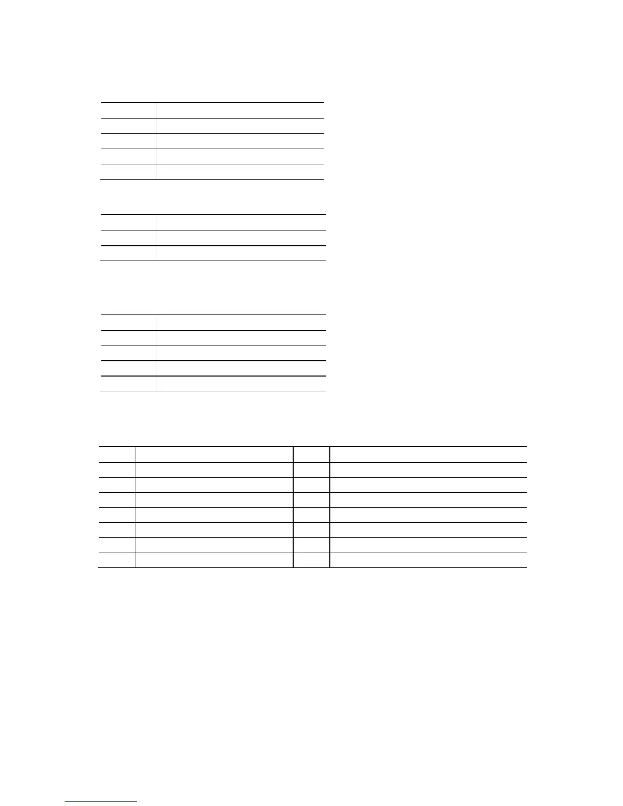
Table 24. S/PDIF Header
Pin Signal Name
1 Ground
2 S/PDIF out
3 Key (no pin)
4 +5 V DC
Table 25. Chassis Intrusion Header
2 Ground
Table 26. Processor, Front, and Rear Chassis
(4-Pin) Fan Headers
Pin Signal Name
1 Ground
3 FAN_TACH
4 FAN_CONTROL
Note: These fan headers use Pulse Width Modulation control for fan speed.
Table 27. LPC Debug Header
3 PLTRST# 4 LFRAME#
5 LAD0 6 LAD1
7 LAD2 8 LAD3
9 GND 10 GND
11 +3.3 V 12 +3.3 V
13 Key (no pin) 14 +3.3 V