Technical Reference
49
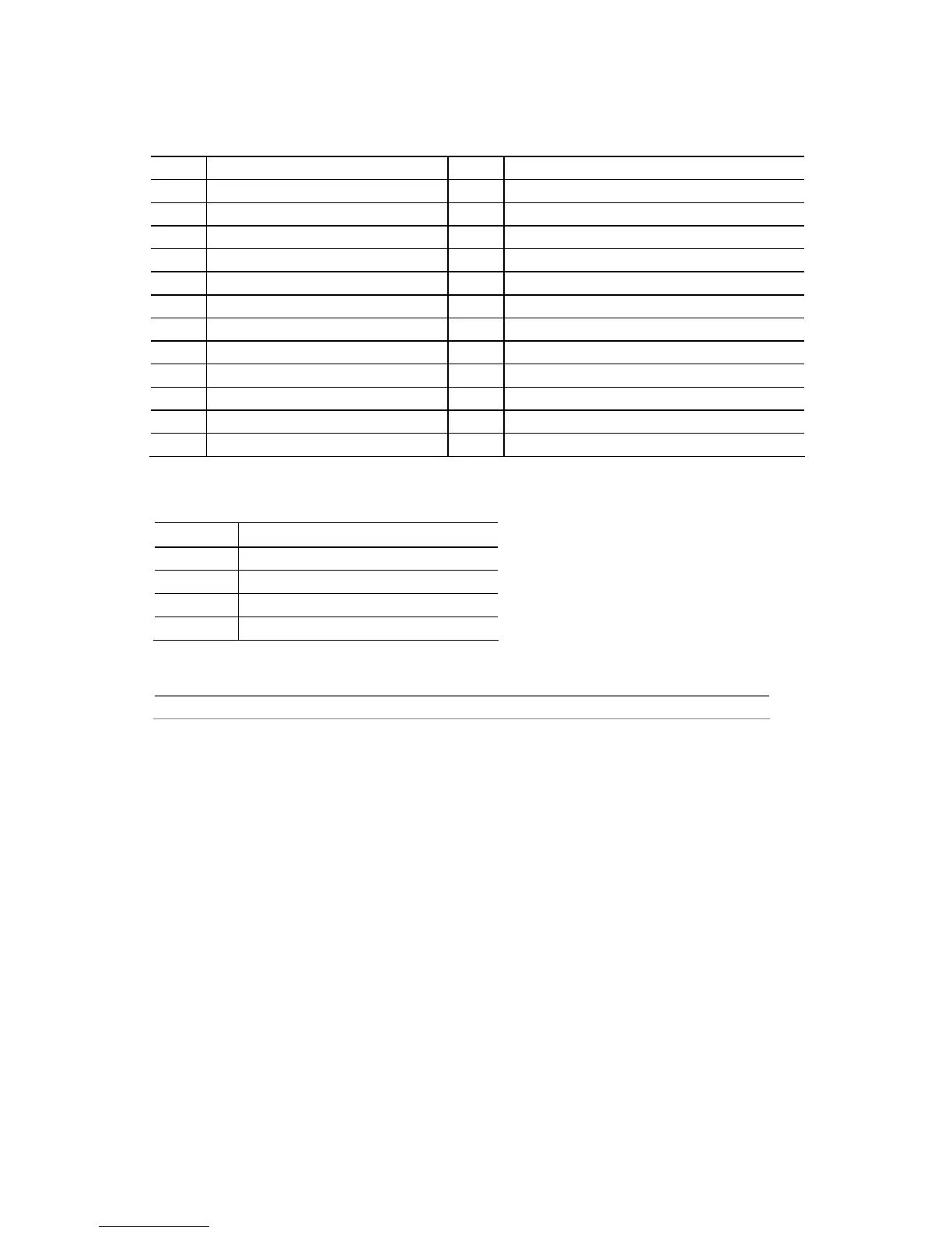
Table 19. Main Power Connector
Pin Signal Name Pin Signal Name
1 +3.3 V 13 +3.3 V
2 +3.3 V 14 -12 V
3 Ground 15 Ground
4 +5 V 16 PS-ON# (power supply remote on/off)
5 Ground 17 Ground
6 +5 V 18 Ground
7 Ground 19 Ground
8 PWRGD (Power Good) 20 No connect
9 +5 V (Standby) 21 +5 V
10 +12 V 22 +5 V
11 +12 V
(Note)
23 +5 V
(Note)
12 2 x 12 connector detect
(Note)
24 Ground
(Note)
Note: When using a 2 x 10 power supply cable, this pin will be unconnected.
Table 20. Auxiliary PCI Express Graphics Power Connector
Pin Signal Name
1 +12 V
2 1 x 4 connector detect
3 Ground
4 +5 V
For information about Refer to
Power supply considerations Section 2.5.1 on page 56
 Loading...