Technical Reference
45
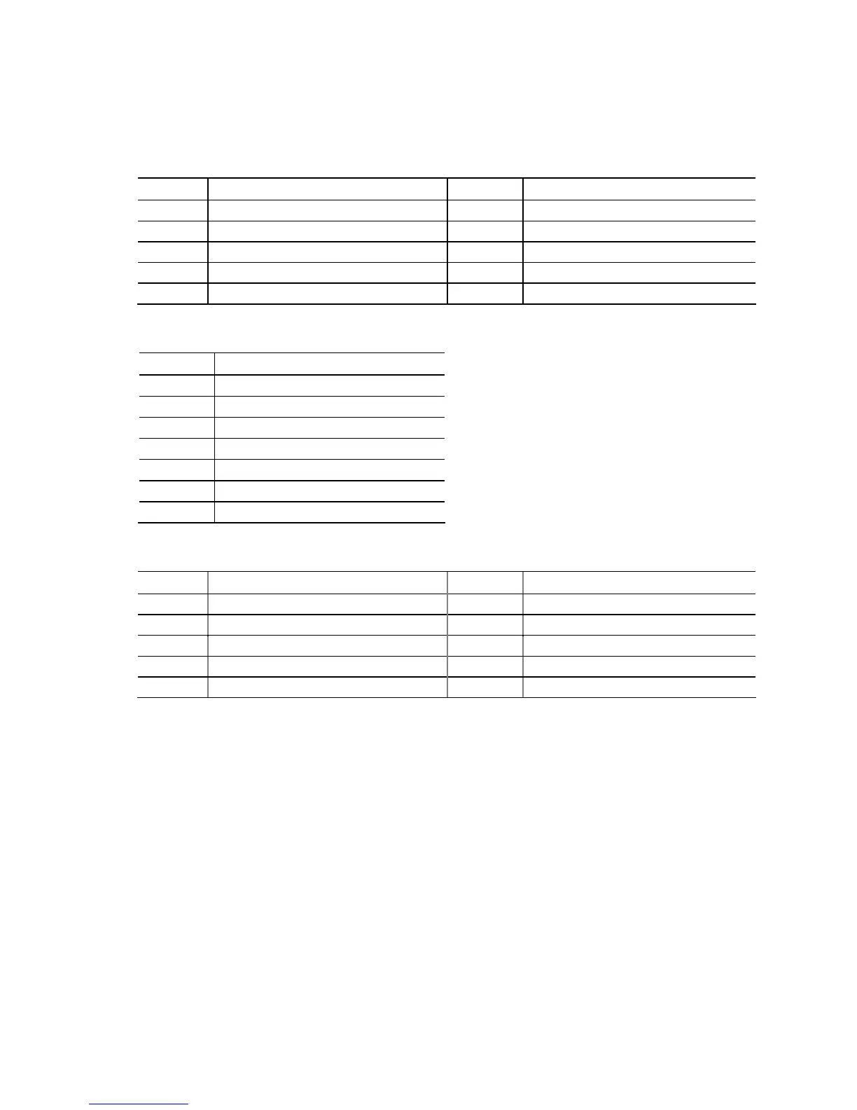
2.2.2.1 Signal Tables for the Connectors and Headers
Table 11. Front Panel Audio Header
Pin Signal Name Pin Signal Name
1 [Port 2] Left channel 2 Ground
3 [Port 2] Right channel 4 PRESENCE# (Dongle present)
5 [Port 1] Right channel 6 [Port 1] SENSE_RETURN
7 SENSE_SEND (Jack detection) 8 Key (no pin)
9 [Port 2] Left channel 10 [Port 2] SENSE_RETURN
Table 12. Serial ATA Connectors
Pin Signal Name
1 Ground
2 TXP
3 TXN
4 Ground
5 RXN
6 RXP
7 Ground
Table 13. Front Panel IEEE 1394a Header
Pin Signal Name Pin Signal Name
1 Data A (positive) 2 Data A (negative)
3 Ground 4 Ground
5 Data B (positive) 6 Data B (negative)
7 +12V_DC 8 +12 V_DC
9 Key (no pin) 10 Ground
Note: The +12 V DC power on the IEEE 1394a header is fused.
 Loading...