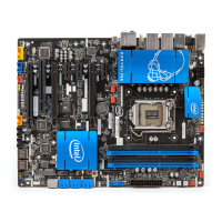
Intel Desktop Board DZ87KLT-75K Technical Product Specification
58
2.2.2.2 Add-in Card Connectors
The board has the following add-in card connectors:
• Three PCI Express 3.0 x16 bus add-in card connectors from the processor
1st PCI Express x16 slot is electrically x8 or x16
2nd PCI Express x16 slot is electrically x8 or disabled
3rd PCI Express x16 slot is electrically x4
• Three PCI Express 2.0 x1 bus add-in card connectors from the PCH
• One Conventional PCI bus add-in card connector from the PCH via a PCI bridge
• One PCI Express Full-/Half-Mini Card slot with support for mSATA
Note: No USB is routed to the PCI Express Full-/Half-Mini Card slot
Note the following considerations for the Conventional PCI bus connector:
• The Conventional PCI bus connectors are bus master capable.
• SMBus signals are routed to the Conventional PCI bus connectors. This enables
Conventional PCI bus add-in boards with SMBus support to access sensor data on
the desktop board. The specific SMBus signals are as follows:
The SMBus clock line is connected to pin A40.
The SMBus data line is connected to pin A41.
NOTE
If the system is overclocked and a video card is installed in the PCI Express x16 (x4
electrical) slot, the system will not complete POST. No POST issue is caused by the
overclocked PCI Express base clock differential compared to the alternate generated
clock use for the PCI Express x16 (x4 electrical) slot.

 Loading...