High-Level Functional Description
The drawback to this design is that the linear supply power drop places a limit on the total power through the
Intel® Edison board and the 3.3 and 1.8 V supplies. The power loss through the charger will be (4.4 to 5 V) • current.
In this case, you should attempt to limit average current through the Intel® Edison board and its power rails to
approximately 0.75 A.
The recharger IC on the Intel® Edison breakout board has input current limit and overtemperature shutdown.
Assure the end design does not trip these protection mechanisms.
Some considerations of the power distribution in the Intel® Edison breakout board:
USB host mode always requires use of an external power adapter. 1.
You are responsible for choosing a suitable battery and following all safety precautions, to prevent 2.
overcharging or charging when the battery temperature is too high. The battery should be at least
300 mAH capacity, due to the 100 mA charging current. Intel recommends battery packs with internal
protection circuits.
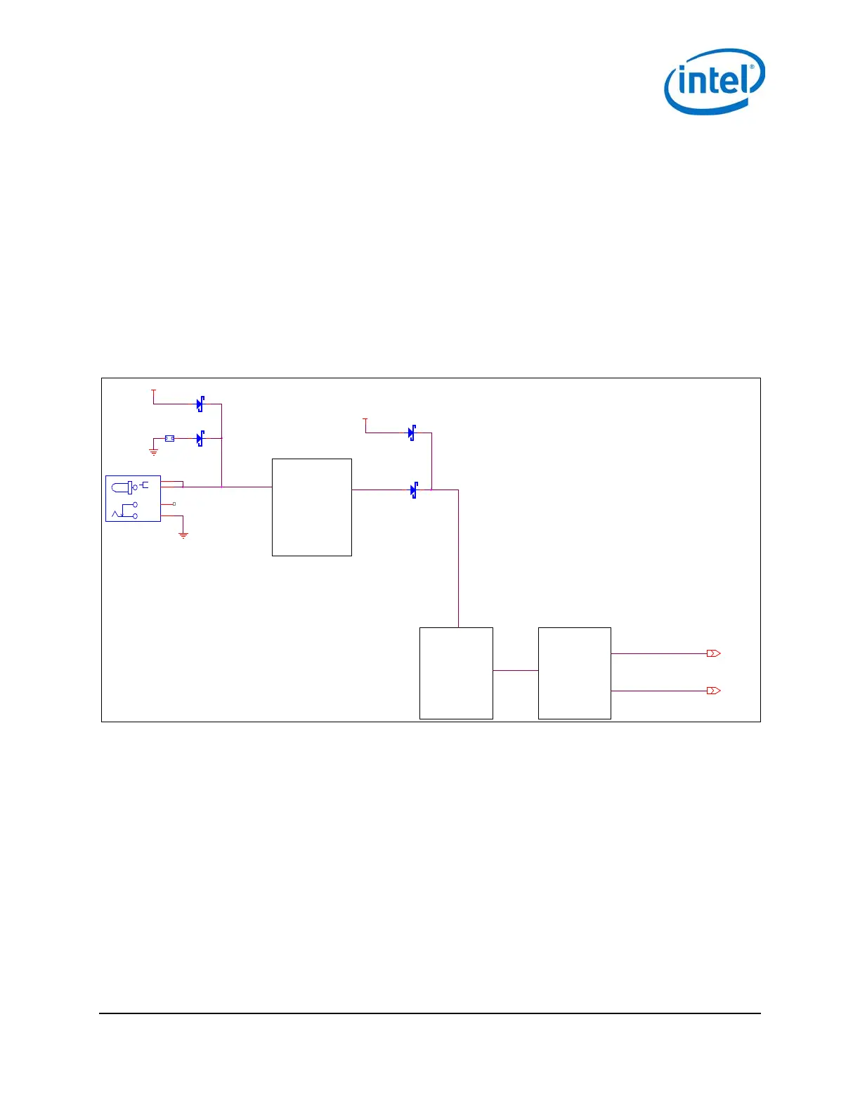
Figure 4 Intel® Edison breakout board expansion board power distribution network
Boot voltage selection – DCIN signal 2.3.1
DCIN is a signal that indicates whether Edison is being powered from a battery or from an external power source.
DCIN also sets the voltage level required on VSYS in order to boot. When DCIN is floating or tied to ground, the
voltage on VSYS must rise from 2.5 to 3.5 V in 10 ms; otherwise the boot is aborted. When the boot is aborted,
power must be cycled below 2.5 V. If DCIN is connected to VSYS, Edison will start to boot when VSYS is above 2.5 V
for 100 ms.
Note: When DCIN is connected to VSYS, boot will occur whenever the voltage is above 2.8 V for 100 ms. The
DCIN signal is attached to VSYS on the PCB.
Note: The absolute minimum voltage to assure Wi-Fi and Bluetooth functionality is 3.15 V.
CHARGING CURRENT = 190ma
TERMINATION CURRENT = 14ma
CR2
D2BW319000
2 1
CHARGE TIMER = 6.2 HOURS
INPUT CURRENT LIMIT = 1 AMP
USB_POWER
CR1
RB160M-40
2 1
5V 1
AMP
SWITCHER
CURRENT
LIMITED
1 AMP
BATTERY
CHARGER
EDISON
3.3V HEADER
1.8V HEADER
CR6 D2BW319000
2 1
CR7
D2BW319000
2 1
VIN_HEADER
J22
DC_JACK_SMT
SHUNT
2
IN_2
3
GND
1
IN_1
4
J21
1 2
Intel® Edison Breakout Board
January 2015 Hardware Guide
Document Number: 331190-006 11