High-Level Functional Description
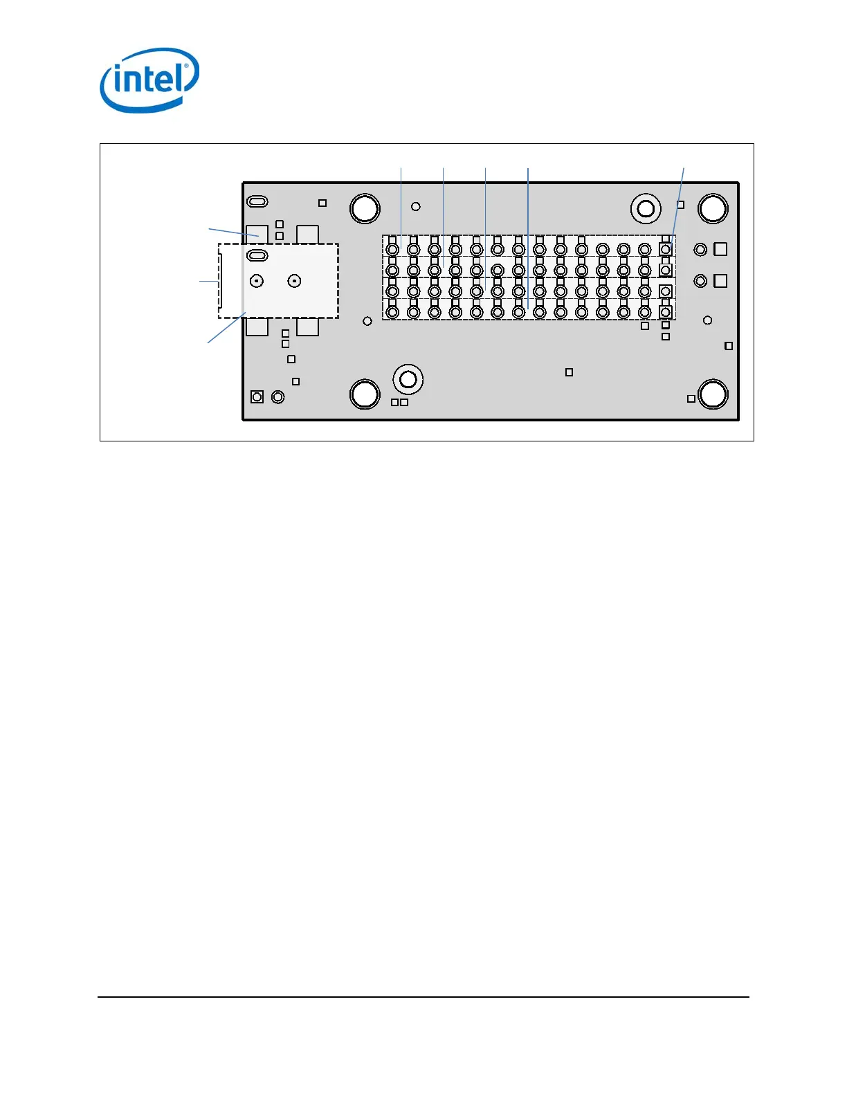
Figure 3 Breakout board jumpers (bottom of board)
J17 J18 J19 J20
Pin 1
J22
Plug end of
power jack
Power jack
(soldered onto
breakout board)
USB interface 2.1.1
The Intel® Edison Breakout Board has a single USB 2.0 interface. This interface is the primary method for
downloading code on J16. It is designed to support full USB “On the Go” (OTG) connections, using the ID signal. If
you plug in a USB micro B connector, the breakout board will act as a USB device, and it will take its power from the
USB connector.
If you plug a USB micro A connector into it, the breakout board will function as a host. When you use the
Intel® Edison Breakout Board as a host in this manner, you must supply external power via J21 or J22. The
breakout board will convert that voltage to supply 5 V to the USB connector.
Note: If you power the breakout board with a battery, it will not supply power as a USB host.
Intel® Edison Breakout Board
Hardware Guide January 2015
8 Document Number: 331190-006