High-Level Functional Description
2.1 Intel® Edison Breakout Board jumpers
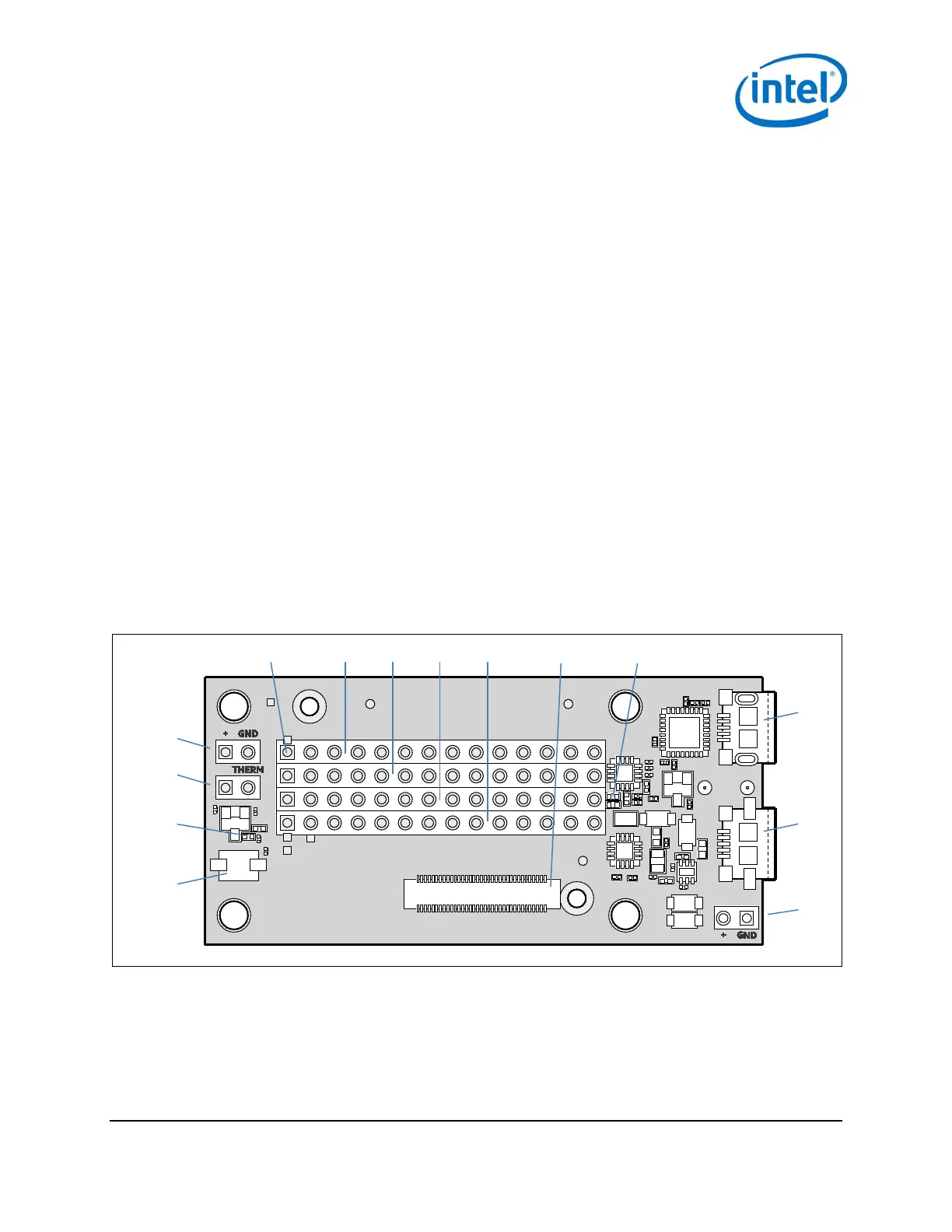
This section explains some of the jumpers on the Intel® Edison Breakout Board. See Figure 2 for jumper locations.
• The left pin (the square one) on J2 is +V battery; the right pin is ground.
• J2 is the battery connector. If you want to power the breakout board with a rechargeable lithium-ion battery,
attach it to J2. (Refer to Figure 2 for battery polarity.) When you attach a rechargeable lithium-ion battery,
the breakout board will recharge the battery whenever power is applied via J21 or J22, or via J3 (when the
board is attached to a USB host).
Note: If you decide to use a battery pack on J2, we recommend a battery with a built-in thermistor. This
thermistor should attach to the charger on the breakout board. If you opt for the built-in thermistor,
remove the jumper on J1 and connect the thermistor to the pin labeled THERM in Figure 2. If you
choose not to use a battery with built-in thermistor, leave the jumper in place.)
• J3 is a micro USB FTDI serial-to-USB converter. The Linux console will output serial stream to this USB
connector.
• J16 is a fully USB compatible, micro AB, OTG (power “on the go”) port. If you plug a micro A cable into this
port, the Intel® Edison module will connect to a PC as the host; if you plug a micro B cable into this port, the
Intel® Edison module will connect to the PC as a device. (See the USB A female to micro A male cable, Digikey
P/N 10-00649 839-1105-ND in Figure 7.)
• For jumpers J17 through J20, the first pin on the left (the square one) is pin 1.
• J21 is the main power input. Apply 7 to 15 VDC with the polarity shown.
• J22 (on the bottom side of the board; see Figure 3) is for a power jack (not installed). You can purchase a
2.5 mm barrel jack (see the mini-breakout power jack in Figure 7, Digikey P/N PJ-002BH-SMT-TR CP-
002BHPJCT-ND) and solder it to the bottom side of the board as shown in Figure 3. The input voltage to J22
is also 7 to 15 VDC.
Figure 2 Breakout board jumpers (top of board)
Pin 1 J17 J18 J19 J20 J7 DS3
J2
J3
J1
DS1
J16
SW1U12
J21
Intel® Edison Breakout Board
January 2015 Hardware Guide
Document Number: 331190-006 7