Intel
®
Galileo
March 2014 Board User Guide
Order Number: 330237-001US 9
Details and Specifications—Intel
®
Galileo Board
2.4 Arduino Connector Pinout Details
The Intel
®
Galileo Board is designed to support shields that operate at either 3.3V or
5V. The core operating voltage of Intel
®
Galileo Board is 3.3V; however, a jumper on
the board enables voltage translation to 5V at the I/O pins. See Section 2.5.3, “VIN
Jumper” on page 14 for details.
The Intel
®
Galileo Board complies with the Arduino Uno Revision 3 pinout as follows:
• 14 digital input/output pins (IO2-IO13, TX, RX):
— Each of the 14 digital pins on Galileo can be used as an input or output, using
pinMode(), digitalWrite(), and digitalRead() functions.
— The pins operate at 3.3 volts or 5 volts. Each pin can source a max of 10 mA or
sink a maximum of 25 mA and has an internal pull-up resistor (disconnected by
default) of 5.6 k to 10 kOhms.
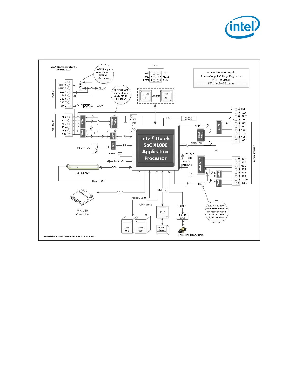
Figure 3. Galileo Board Connection Diagram