Intel
®
Galileo Board—Overview
Intel
®
Galileo
Board User Guide March 2014
6 Order Number: 330237-001US
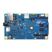
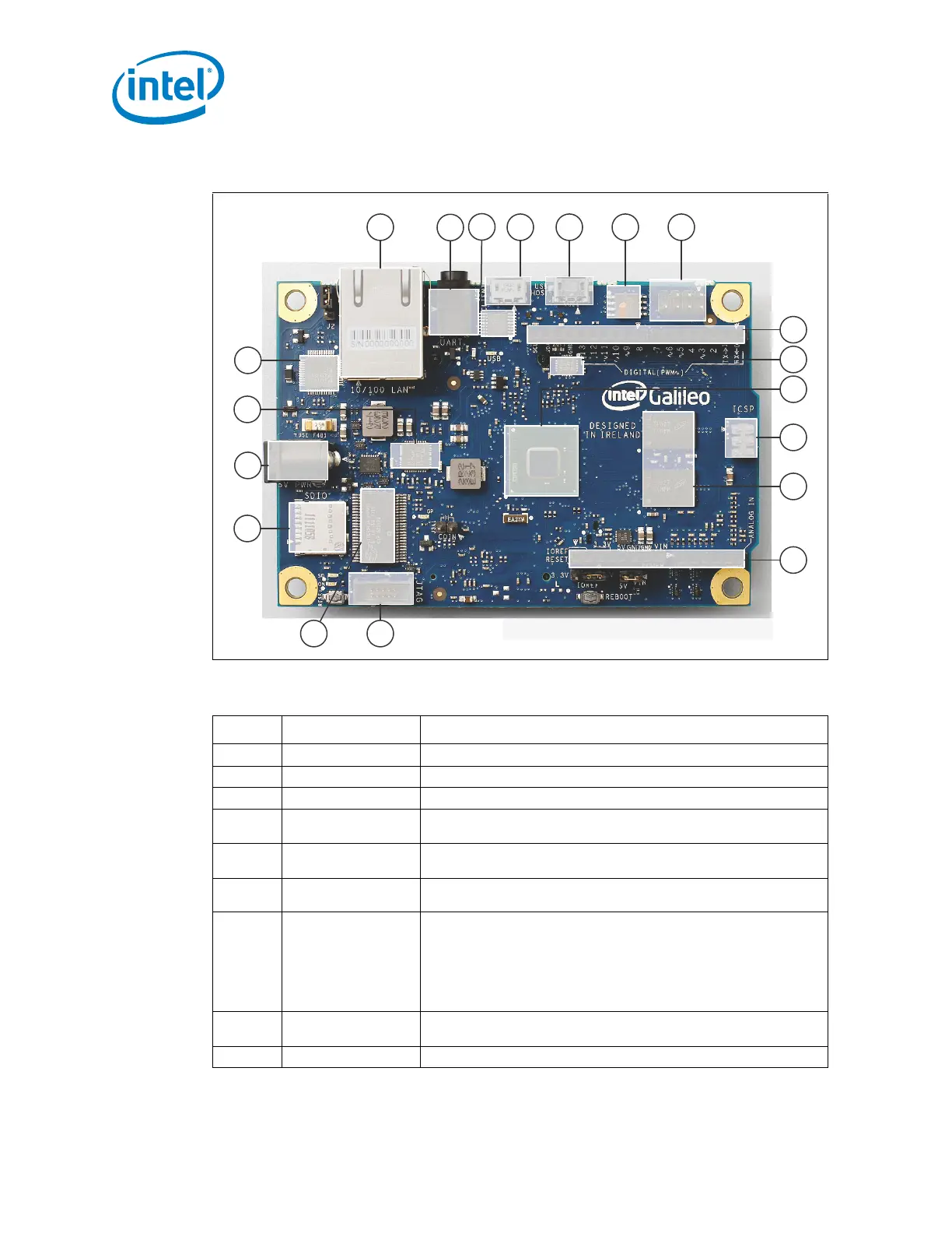
Figure 2. Key Components
,QWHO
4XDUN6R&
;
86%
&OLHQW
-7$*
'HEXJ3RUW
56
6HULDO
3RUW
(WKHUQHW
3RUW
9
3RZHU
86%
+RVW
0LFUR
6'VORW
63,)ODVK
3URJUDP
3RUW
$'&
3&,H*HQPLQLFDUGVORWRQEDFNRIERDUGÆ
$UGXLQR,QWHUIDFH
,&63
*3,2
([SDQGHU
(WK
3+<
0%
''5
5$0
9ROWDJH
5HJXODWRU
56
63,
)ODVK
$UGXLQR,QWHUIDFH
Table 1. Description of Key Components (Sheet 1 of 2)
Number Component Description
1 Ethernet Port 10/100 Ethernet connector
2 RS-232 Serial Port 3-pin 3.5mm jack (not audio)
3 RS-232 RS-232 transceiver
4 USB 2.0 Client
USB Client connector (Micro-USB Type B): a fully compliant USB 2.0
Device controller, typically used for programming
5 USB 2.0 Host
USB 2.0 Host connector (Micro-USB Type AB): supports up to 128 USB
end point devices
6 SPI Flash
8 MByte Legacy SPI Flash to store the firmware (or bootloader) and the
latest sketch.
7 SPI Flash Program Port
7-pin header for Serial Peripheral Interface (SPI) programming
Defaults to 4 MHz to support Arduino Uno shields. Programmable up to
25 MHz.
Note: The board has a native SPI controller, however, it will act as a
master and not as an SPI slave. Therefore, it cannot be a SPI
slave to another SPI master. It can act, however, as a slave
device via the USB Client connector.
8Shield Interface
Complies with Arduino Uno Revision 3 shield pinout. See Section 2.4 for
details.
9 ADC Analog to Digital converter