Intel
®
Galileo Board—Details and Specifications
Intel
®
Galileo
Board User Guide March 2014
8 Order Number: 330237-001US
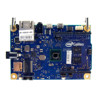
2.0 Details and Specifications
2.1 Physical Characteristics
The Intel
®
Galileo Board is 10 cm long and 7 cm wide respectively, with the USB
connectors, UART jack, Ethernet connector, and power jack extending beyond the
former dimension. Four screw holes (4 mm diameter) allow the board to be attached to
a surface or case.
Note: The distance between digital pins 7 and 8 is 160 mil (0.16"); it is not an even multiple
of the 100 mil spacing of the other pins.
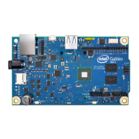
2.2 Electrical Summary
The Intel
®
Galileo Board is powered via an AC-to-DC adapter, connected by plugging a
2.1 mm center-positive plug into the board's power jack. The recommended output
rating of the power adapter is 5V at up to 3A.
2.3 Schematic and Reference Design
Figure 3 shows a connection diagram for the Intel
®
Galileo Board.
For complete board details, see:
• Galileo Schematic in PDF:
https://communities.intel.com/docs/DOC-21822
• Galileo Reference Design: zip file containing Allegro Board file
https://communities.intel.com/docs/DOC-21824
Input Voltage (recommended) 5V
Input Voltage (limits) 5V
Digital I/O Pins 14 (of which 6 provide PWM output)
Analog Input Pins 6
Total DC Output Current on all I/O lines 80 mA
DC Current for 3.3V Pin 800 mA
DC Current for 5V Pin 800 mA