25
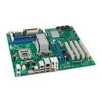
(8) Floppy drive Connector (34-pin block): FLOPPY
This connector supports the provided floppy drive ribbon cable. After connecting the
single plug end to motherboard, connect the two plugs at other end to the floppy drives.
Floppy Drive Connector
Pin 1
FLOPPY
(White)
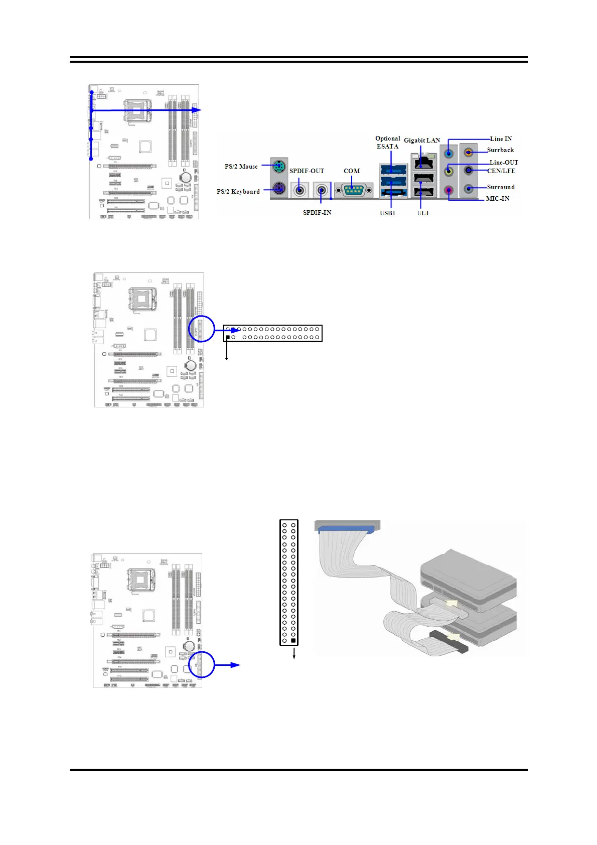
(9) Primary IDE Connector (40-pin block): IDE1
This connector supports the provided IDE hard disk ribbon cable. After connecting the
single plug end to motherboard, connect the two plugs at other end to your hard disk(s).
If you install two hard disks, you must configure the second drive to Slave mode by
setting its jumpers accordingly. Please refer to the documentation of your hard disk for
the jumper settings.
Primary IDE Connector(Blue)
Pin 1
IDE1
•
Two hard disks can be connected to each connector. The first HDD is referred to as the
“Master” and the second HDD is referred to as the “Slave”.