Intel® Server Board S1200BT TPS Intel® Light Guided Diagnostics
Revision 1.0
Intel order number G13326-003
9. Intel
®
Light Guided Diagnostics
The server board has several on-board diagnostic LEDs to assist in troubleshooting board-level
issues. This section shows where each LED is located on the server board and describes the
function of each LED.
9.1 System Status LED (Only for S1200BTL)
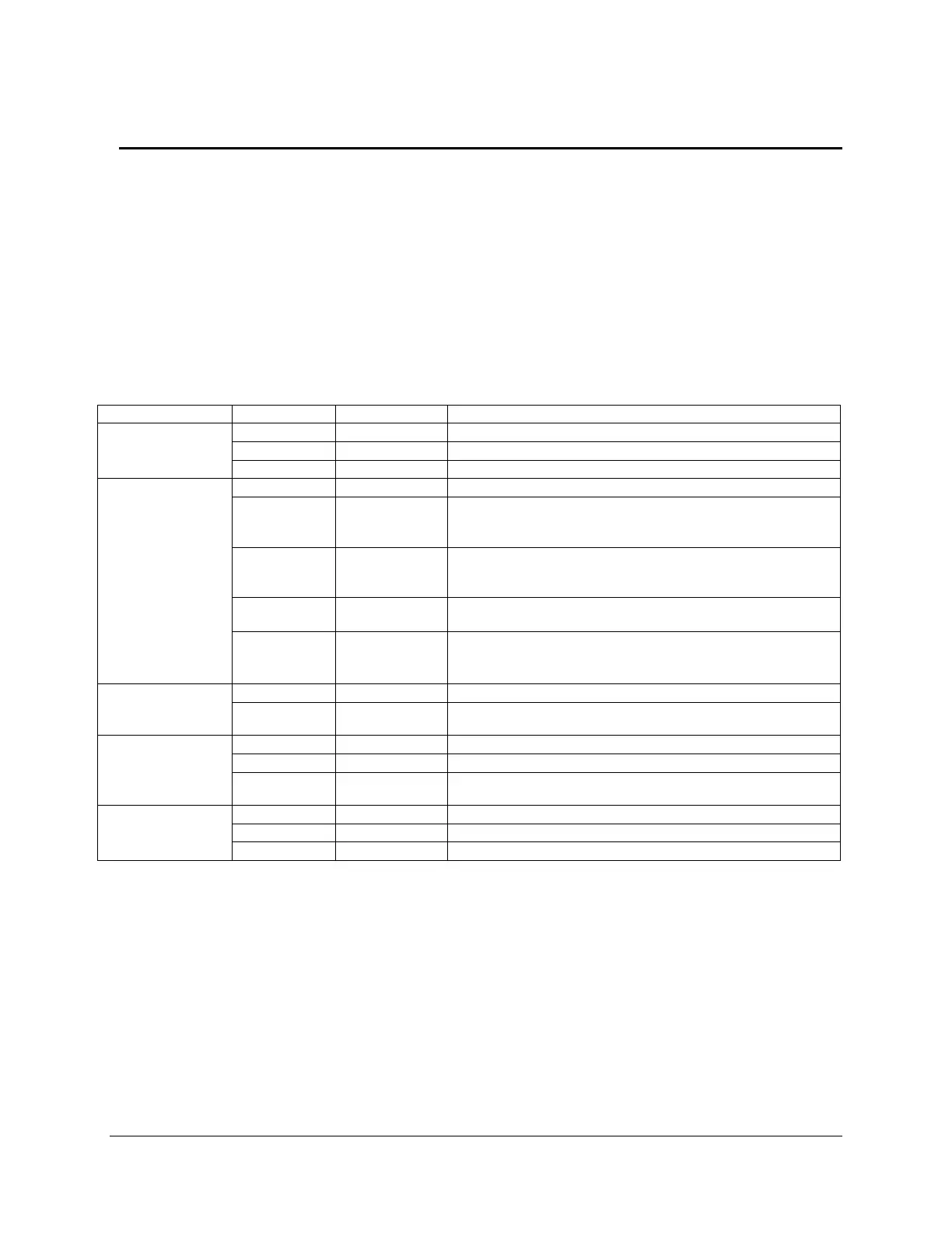
The server board provides a system status indicator LED on the front panel. This indicator LED
has specific states and corresponding interpretation as shown in the following table:
Table 44. Front Panel LED Behavior Summary
S1 sleep or S3 standby only for workstation baseboards
Off (also sleep S4/S5 modes)
System ready, but degraded: redundancy lost such as PS or
fan failure; non-critical temp/voltage threshold; battery
failure; or predictive PS failure.
Critical alarm: Voltage, thermal, or power fault; CPU
missing; insufficient power unit redundancy resource offset
asserted
Non-Critical failure: Critical temp/voltage threshold; VDR hot
asserted; min number fans not present or failed
AC power off: System unplugged
AC power on: System powered off and in standby, no prior
degraded\non-critical\critical state
Front panel chassis ID button pressed
Unit selected for identification via software
9.2 Post Code Diagnostic LEDs
During the system boot process, the BIOS executes several platform configuration processes,
each of which is assigned a specific hex POST code number. As each configuration routine is
started, the BIOS displays the POST code on the POST code diagnostic LEDs found on the
back edge of the server board. To assist in troubleshooting a system hang during the POST
process, the diagnostic LEDs can be used to identify the last POST process executed.

 Loading...


