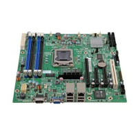
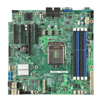
List of Figures Intel® Server Board S1200BT TPS
Revision 1.0
Intel order number G13326-003
List of Figures
Figure 1. Intel
®
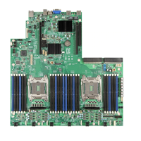
Server Board S1200BTL Picture ......................................................................... 4
Figure 2. Intel
®
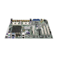
Server Board S1200BTS Picture ........................................................................ 5
Figure 3. Intel
®
Server Board S1200BTL Layout ......................................................................... 6
Figure 4. Intel
®
Server Board S1200BTS Layout ......................................................................... 7
Figure 5. Intel
®
Server Board S1200BTL – Hole and Component Positions ................................ 9
Figure 6. Intel
®
Server Board S1200BTL – Major Connector Pin Location (1 of 2) .................... 10
Figure 7. Intel
®
Server Board S1200BTL – Major Connector Pin Location (2 of 2) .................... 11
Figure 8. Intel
®
Server Board S1200BTL – Primary Side Keepout Zone ................................... 12
Figure 9. Intel
®
Server Board S1200BTL – Secondary Side Keepout Zone ............................... 13
Figure 10. Intel
®
Server Board S1200BT Rear I/O Layout ......................................................... 14
Figure 11. Intel
®
Server Board S1200BTL Functional Block Diagram ....................................... 15
Figure 12. Intel
®
Server Board S1200BTS Functional Block Diagram ....................................... 16
Figure 13. Integrated BMC Hardware ....................................................................................... 26
Figure 14. Server Management Bus (SMBUS) Block Diagram.................................................. 32
Figure 15. Main Screen ............................................................................................................. 56
Figure 16. Advanced Screen ..................................................................................................... 59
Figure 17. Processor Configuration Screen .............................................................................. 62
Figure 18. Memory Configuration Screen.................................................................................. 68
Figure 19. Mass Storage Controller Configuration Screen ........................................................ 71
Figure 20. Serial Port Configuration Screen .............................................................................. 72
Figure 21. USB Configuration Screen ....................................................................................... 73
Figure 22. PCI Configuration Screen ........................................................................................ 74
Figure 23. System Acoustic and Performance Configuration .................................................... 75
Figure 24. Security Screen ........................................................................................................ 75
Figure 25. Server Management Screen (S1200BTL) ................................................................ 76
Figure 26. Server Management Screen (S1200BTS) ................................................................ 77
Figure 27. Console Redirection Screen..................................................................................... 77
Figure 28. System Information Screen (S1200BTL) .................................................................. 78
Figure 29.System Information Screen (S1200BTS) .................................................................. 79
Figure 30. BMC LAN Configuration Screen (S1200BTL)........................................................... 80
Figure 31. Hardware Monitor Screen, Auto Fan Control (S1200BTS) ....................................... 81
Figure 32. Hardware Monitor Screen, Manual Fan Control (S1200BTS) ................................... 81

 Loading...
